A general introduction to AVR Microcontrollers.
Designed by:
Colin "MrSwirlyEyes" Keef
todo. What is an AVR microcontroller, and what can you do with it? Why do you want to know how to use them? Who is intrested in using them (target audience)? Throughout this AVR Microcontroller tutorial, we will be utilizing the Arduino IDE. We will also program our AVR microcontrollers using two methods: (1) The Arduino UNO configured as an ISP (In-System Programmer) and (2) the Sparkfun Pocket AVR Programmer, which does the work of programming our AVR microcontrollers for us.
| DEVICE | VENDOR URL | QUANTITY | NOTES |
|---|---|---|---|
| Arduino UNO R3 | Digikey | 2 | May use other variants, but may need minor changes to code. |
| USB Cable (A Male to B Male) | Digikey | 2 | |
| [Optional] POCKET AVR PROGRAMMER | Digikey | 1 | Optional if using Arduino UNO as ISP. Used to bootload AVR microcontrollers. |
| [Optional] USB Cable (A Male to Mini B Male) | Digikey | 1 | Accessory to AVR Pocket Programmer. |
In this module, we will install the AVR bootloaders, or cores, for either ATMEGA (e.g. ATMEGA328p, ATMEGA2560) or ATtiny (e.g. ATtinyX5, ATtinyX4, ATtinyX313) devices into our Arduino IDE. We will introduce the bootloader installed, and explain the SPI (Serial Peripheral Interface) pins that exist on every AVR variant, which are necessary for bootloading (and often programming) all AVR microcontrollers. The AVR microcontrollers are programmed via SPI (Serial Peripheral Interface) pins connected between the programming device (Arduino UNO as an ISP or the Sparkfun Pocket AVR Programmer) and the target AVR microcontroller.
We are going to cover how to program two classes of microcontrollers: ATtiny AVR microcontrollers and ATMEGA AVR microcontrollers. At their core, they are very similar. However, there are some subtle differences that warrant separation, so follow the path appropriate for your application or microcontroller - or, learn about both, if you really want to be baller.
Open the Arduino IDE.
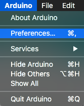
Navigate to Arduino > Preferences. Click on Additional Boards Manager URL. Then paste the following URL into the window that pops up:
The Arduino Preferences window will open. Towards the bottom, click on the Additional Boards Manager URL icon to the right of the textbox.
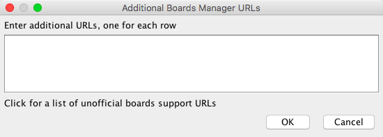
A smaller pop-up window will open where you can paste URLs for additional boards to integrate into your Arduino IDE. Copy and paste the following URL into the window that pops up.
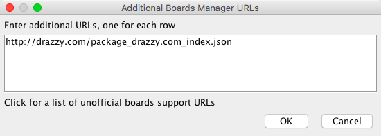
http://drazzy.com/package_drazzy.com_index.jsonClick OK to exit both the Additional Boards Manager URL pop-up window and the Arduino Preferences and return to the Arduino IDE.
This URL is a json string that contains metadata for SpenceKonde's ATtinyCore (https://github.com/SpenceKonde/ATTinyCore). By placing the URL here, we can install the ATtinyCore to integrate additional 'boards' into the Arduino IDE so we may program these boards like we would an Arduino or another supported microcontroller through the Arduino environment.
If you have additional boards you wish to install, you can place other URLS on separate lines here (e.g. Sparkfun boards).
These steps have made it so that Arduino IDE knows where to find informatino about the boards, but we haven't actually installed them. Let's fix that.
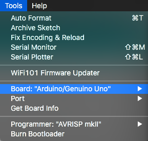
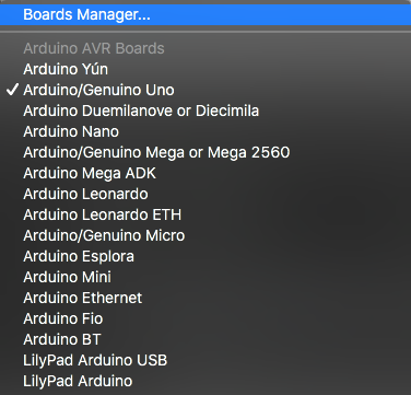
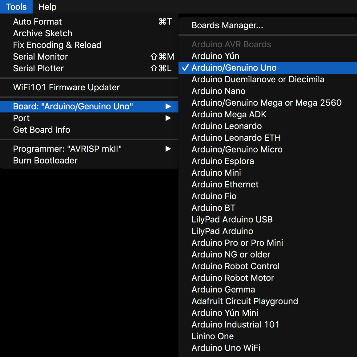
Navigate to Tools > Board: “...” > Boards Manager...
Where '...' will be the last board you programmed using Arduino (e.g. Arduino/Genduino UNO).
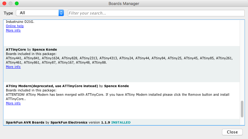
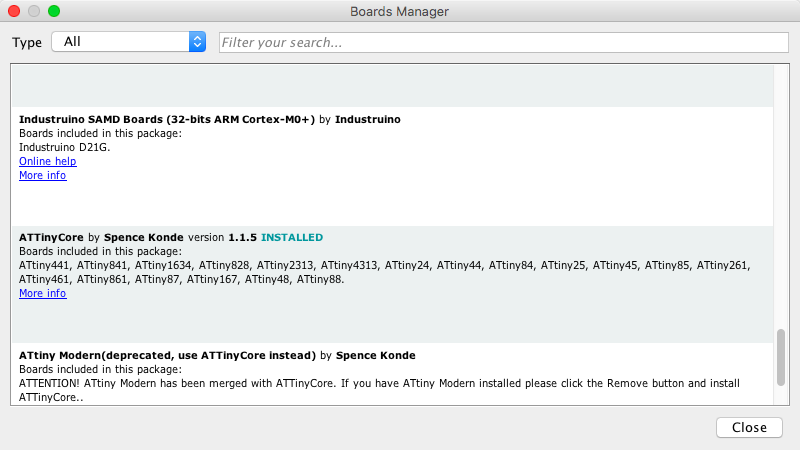
The Boards Manager window will open. Scroll down until you see the row for ATtinyCore by SpenceKonde.
It might take a few seconds for the window to become responsive while it checks for updates for your board libraries.
Click anywhere in the ATtinyCore by SpenceKonde row to reveal the installation options.
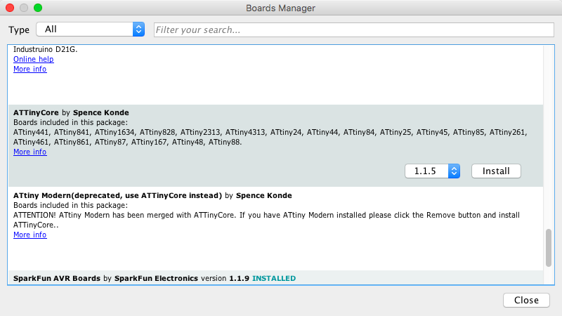
Observe a drop-down menu appears, for selecting an ATtinyCore version, with an Install button. Select the latest version of the ATtinyCore to install. Click Install.
At the time of this writing, the latest version is 1.1.5.
After several seconds, the boards will be installed. The row for ATtinyCore by SpenceKonde should now display the current version installed.
Check back to see if there are updates for this package from time to time.
With the installation completed, exit the Boards Manager by clicking Close and restart the Arduino IDE.
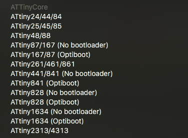
With the Arduino IDE open, navigate to Tools > Board: “...” and observe the newly installed ATtinyCore boards. There are several variants of ATtiny microcontrollers (MCUs).
At this point the ATtinyCore, with a massive collection of various ATtiny micrcontrollers, is available to program via the Arduino IDE!
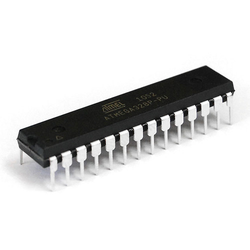
Unfortunately, at this time, we have not explored many different ATMEGA microcontrollers. We have only tested ATMEGA328p microcontroller extensively (the same microcontroller at the heart of the Arduino UNO). In the future we hope to explore several ATMEGA variants and find/create the appropriate bootloader.
Fortunately, if you are working with the ATMEGA328p microcontroller, you can essentially treat it as an Arduino UNO, and since the Arduino UNO already comes with its own bootloader, we do not have to do any work here. You already have the ATMEGA328p bootloader/core installed.
With the appropriate AVR microcontroller core installed, we can explore the board settings for these microcontrollers.
When selecting an AVR microcontroller board to program, several options may appear that are not common to most microcontrollers (like Arduino UNO, which does not have any particular board settings to configure). In this module, we will briefly touch on some of these settings to get you familiar with what they do and can be used for. We have not explicitly tested these in great detail, so we encourage you to test them out for yourselves.
We will also briefly go over the process for determining the board settings for the AVR microcontrollers where applicable. For the ATMEGA variants we will only cover the ATMEGA328p at this time.
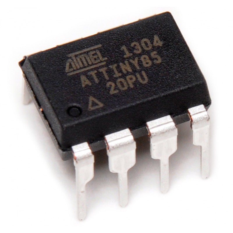
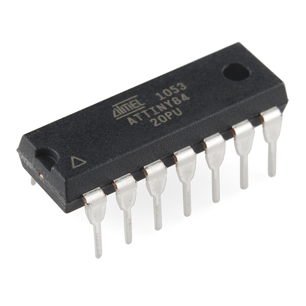
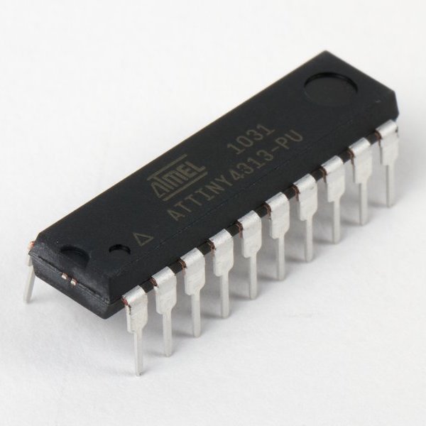
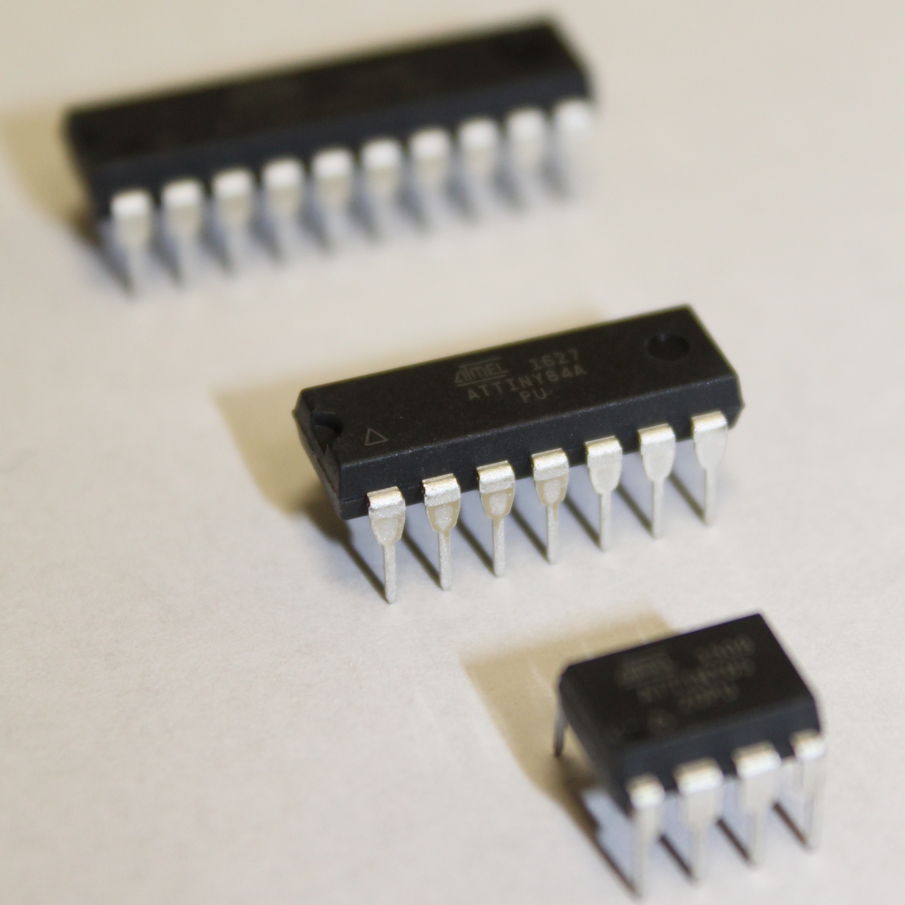
For the ATtiny variants, we will cover the ATtinyX5, ATtinyX4, and ATtinyX313 - however, this same process applies to all of the other ATtiny variants in the ATtinyCore. Observe, there are a few variants for each of these series. The X is a number that represents the amount of flash memory available on the particular chip (in KB, kilobytes). The devices within a series are all identical except in price and amount of memory. However, the X5, X4, and X313 series are quite different from each other, so we will explore each of them separately.
You always want to choose the microcontroller that is the best fit for your application, so pay attention to the differences between these devices!
We will now briefly go over some of the settings that common across most of the ATtiny variants. In particular, we will cover the ATtinyX4, ATtinyX5, and ATtinyX313 variants.
Navigate to the ATtinyCore board variants: Tools > Board: “...”
If you select the ATtiny25/45/85 (or as we will refer to it: ATtinyX5), ATtiny24/44/84 (or ATtinyX4), or ATtiny2313/4313 (or ATtinyX313) the board will be selected.
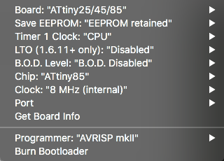
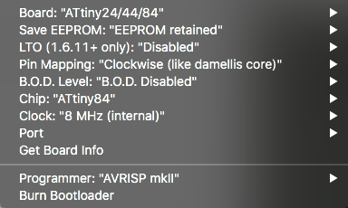
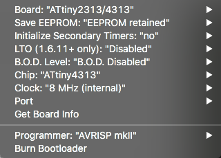
Then navigate to Tools and observe the selected ATtiny board settings. The following image shows the settings for each of the aforementioned ATtiny variants.
Amongst these ATtiny variants, there are several settings that are common/similar between them. We will briefly explain some of the significances and uses for each of these settings. Most of them can be left in their default state, however, a few of these settings are extremely important and if used inappropriately can potentially brick your microchip - that is, render your chip (practically) useless.
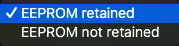
Controls whether the non-volatile memory EEPROM (Electrically Erasable Programmable Read-Only Memory) is erased during a chip erase cycle.
For general use, keep on default setting: EEPROM retained.
Link-Time Optimization (LTO) reduces the compiled size of the code you upload to the ATtiny microchip. Generally, results in using less flash memory.
For general use, keep on default setting: Disabled.
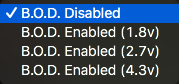
Brown-Out Detection (B.O.D.) Level is the trigger voltage for Brown Out Detection. B.O.D. continuously monitors VCC, and below the chosen B.O.D. voltage level, the ATtiny will be held in the reset state. That is, when the voltage across the ATtiny drops below the set threshold, and thus becomes insufficiently powered, the voltage may be too low to reliably run at the set clock speed.
Without B.O.D. enabled, the chip may behave erratically or fall into an unresponsive state until manually reset or power cycled. Other consequences include erasure, or overwriting the RAM and EEPROM.
Enabling B.O.D. level at a particular voltage forces the ATtiny to be held in reset until the voltage returns to the particular voltage level chosen. It is particularly important for any data-logging and trying to protect data from being corrupted.
For general use, keep on default setting: B.O.D. Disabled.
Chip is simply which variant of the chip you are programming, dependent on which ATtiny board is selected.
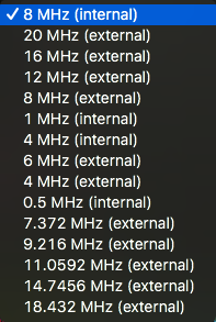
The clock sets how fast the ATtiny will operate, in hertz (Hz). The faster the clock speed, the more commands that can be executed in a given period of time, and the more power it will consume.
Observe that there are options for internal and external clock rates. The ATtiny as a standalone microcontroller will support any of the internal clock speeds. If you wish to run the board faster, at one of the listed external clock rates, you will need to attach a(n) (physical) external crystal oscillator to the ATtiny.
Set Clock to 8 MHz (internal).
For general use, keep on one of the default internal settings. (e.g. 8 MHz (internal)).
If you do external on accident, you will brick (effectively disable or render useless) the ATtiny until we connect the corresponding external clock. Do NOT select any external clock rates unless you already have an external oscillator configured.
Now that we have covered the settings that are common to all the ATtiny variants, there are settings that are unique to one or a few of the ATtiny variants. We encourage exploring these settings when appropriate. You can get the best information from SpenceKonde's ATtinyCore GitHub (see Resources & References). We will also make a brief mention of them when we talk about particular ATtiny modules that we work with.
Since the ATMEGA328p bootloader we are covering is the bootloader for the Arduino UNO, there are no configurable settings (recall that the Arduino UNO runs with a specific bootlaoder). Giving a bootloader with a significant change (e.g. changing the clock) may cause the Arduino UNO to operate incorrectly.
With the appropriate AVR microcontroller board settings covered, we can explore the procedure for bootloading these microcontrollers.
When you receive an AVR microcontroller from a distributor or vendor, they generally have some bootloader pre-flashed onto the microchip. This flash may have particular settings, and you can't really know what will be flashed on it other than that it relies on its own internal clock, so you can program them without any specialized hardware (e.g. an external crystal oscillator).
What we will do is bootload the AVR microcontroller. That is, we are going to set the fuses of the AVR microcontroller with the settings we desire. We set them in the previous section, but if we want the AVR microcontroller to have them, we need to burn them into the microcontroller through a process called burn bootloader or just bootloading.
Not remembering to burn the bootloader will generally result in weird behavior. Most notably, the timers will not operate as expected, and the delay function will not be accurate.
The takeaway here is the explicit process of bootloading (and programming in some cases) an AVR microcontroller, and remembering to ALWAYS bootload every AVR microcontroller chip. It is OK to do it more than once if you are not sure you programmed it - it does not hurt the microcontroller. You can also change the fuse settings and burn the bootloader again.
The following module is generalized for any AVR microcontroller, so there is no separation between ATtiny and ATMEGA variants.
There are several ways to bootload AVR microcontrollers. The most common way is to buy a 3rd party device that you connect to the AVR microcontroller, and then use the Arduino IDE, the Terminal, or a 3rd party application to bootload or flash/program the AVR microcontroller. A cheaper, and arguably more satisfiying approach, is using an Arduino UNO to program an AVR microcontroller chip. This method maximizes the mileage you can get out of an Arduino UNO. If you have a through-hole DIP-packaged AVR microcontroller, then you can make the necessary connections on a breadboard and the flash the ATtiny using the Arduino UNO. If your AVR microcontroller is integrated onto a PCB, then you use the ISP header that you (should) have on the board.
In this module, we will outline two methods of programming an AVR microcontroller: using the Arduino UNO directly via breadboard by configuring the Arduino as an ISP (In-System Programmer), and using a Sparkfun Pocket AVR Programmer.
In order to better understand the Arduino UNO configured as an ISP (In-System Programmer), we're going to explore the Arduino UNO in more detail than you may have before. Remember, at the heart of the Arduino UNO is the ATMEGA328p - an AVR microcontroller.
The Arduino UNO development board has the ATMEGA328p as its microcontroller. The family of ATMEGA boards are related to ATtiny boards - both have 'AT-' in the name, which denotes ATMEL (now Microchip), the company that designed and manufacture these micrcontrollers. The ATMEGA microcontrollers are generally more powerful than the ATtiny microcontrollers, but the way we interface with and program them are identical.
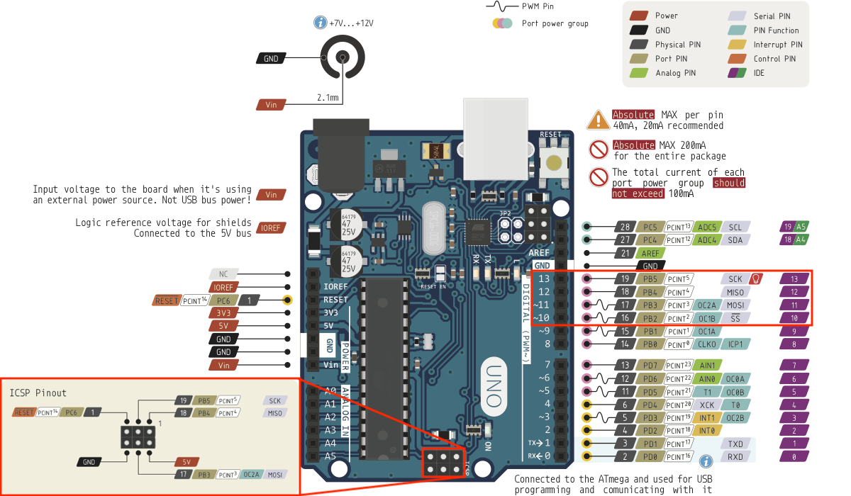
The following diagram illustrates the Arduino UNO R3 pinout for reference:
This image may be overwhelming as it details a lot about the Arduino UNO that is not necessary for most casual makers. However, it shows information that is important for programming AVR microcontrollers. Let's investigate some of these more powerful features as well as some basic features of the Arduino UNO development board.
The Arduino UNO development board conveniently groups and labels these pin (or header) rails:
analogRead function in the Arduino IDE.The '~' denotes a PWM capable pin
A closer look at the pinout diagram reveals many interesting labels for each of the pins. We are going to focus on the ones that are of particular importance for programming AVR microcontrollers. These pins are the Serial Peripheral Interface (SPI). SPI is a synchronized data protocol used by microcontrollers to communicate with one another over short (physical) distances. In an SPI connection, there is always one Master (e.g. Arduino UNO) that will control (or program in our case) peripheral devices, namely, the target AVR microcontroller.
The SPI pins are named and labeled as follows:
Find these pins on the Arduino UNO pinout diagram below and be aware of their location on your Arduino UNO and other AVR microcontrollers. In the same diagram, we highlight the In Circuit Serial Programmer (ICSP) header. This header appears in many AVR microcontroller development boards. It is a standardized interface for bootloading and programming AVR microcontrollers.
Observe that the ICSP Pinout header and digital pins 10-13 are connected together!
The AVR Pocket Programmer uses ths ICSP header! We will be using an Arduino UNO here without the standard header, but functionally we are doing the same thing without the extra hardware purchase.
The SPI is what we will use to program the AVR microcontrollers when we configure the Arduino UNO as an In-System Programmer ISP). This makes the Arduino UNO a little bit more powerful. The ability to program other AVR microcontrollers using an AVR microcontroller...whoa...deep. Let us now proceed to configuring the Arduino as an ISP.
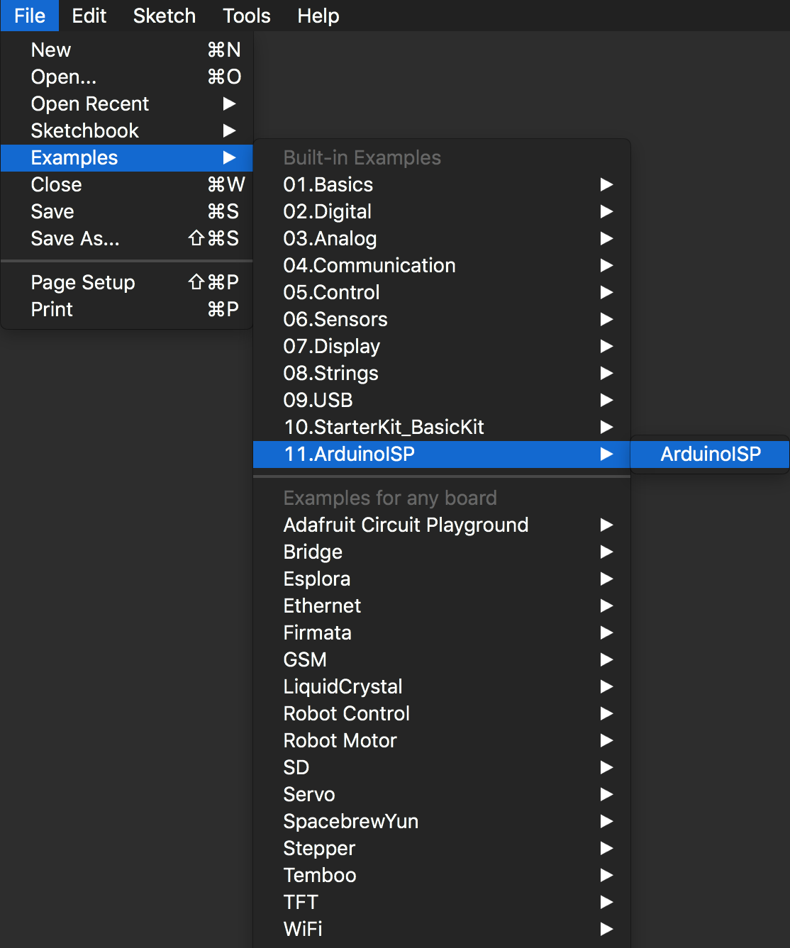
Configuring the Arduino UNO as an ISP (In-System Programmer) is extremely easy. Arduino already supports this feature and has their own Example Sketch for programming the Arduino UNO to be an ISP.
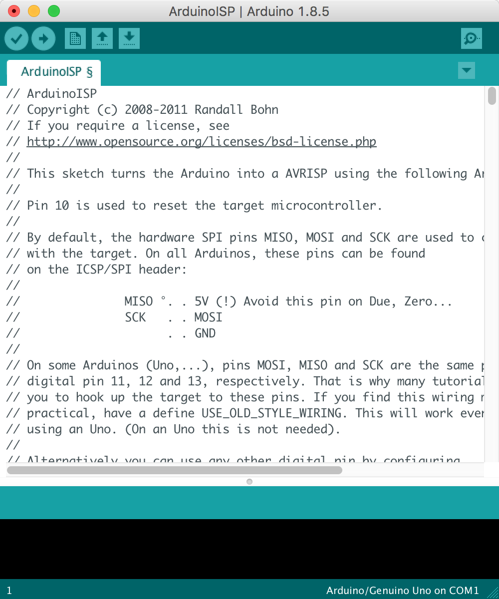
Launch the Arduino UNO IDE. Navigate through File > Examples > 11.ArduinoISP and select the ArduinoISP sketch.
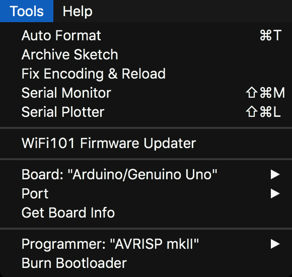
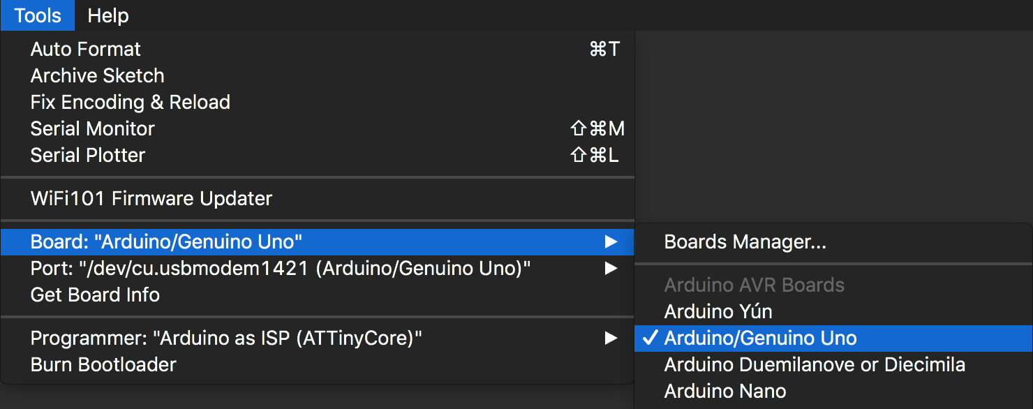
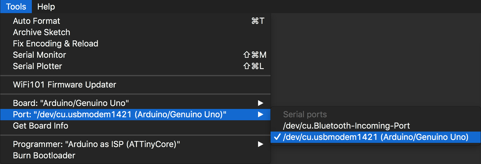
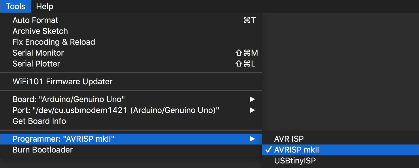
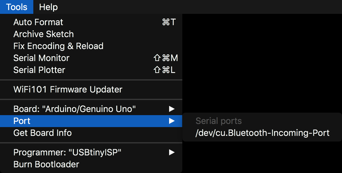
Before we program the Arduino UNO with the ArduinoISP sketch, we need to set the following settings in the Tools menu:
Port names are variable across different operating systems (Windows, Mac OS, and Linux) and physical USB ports.
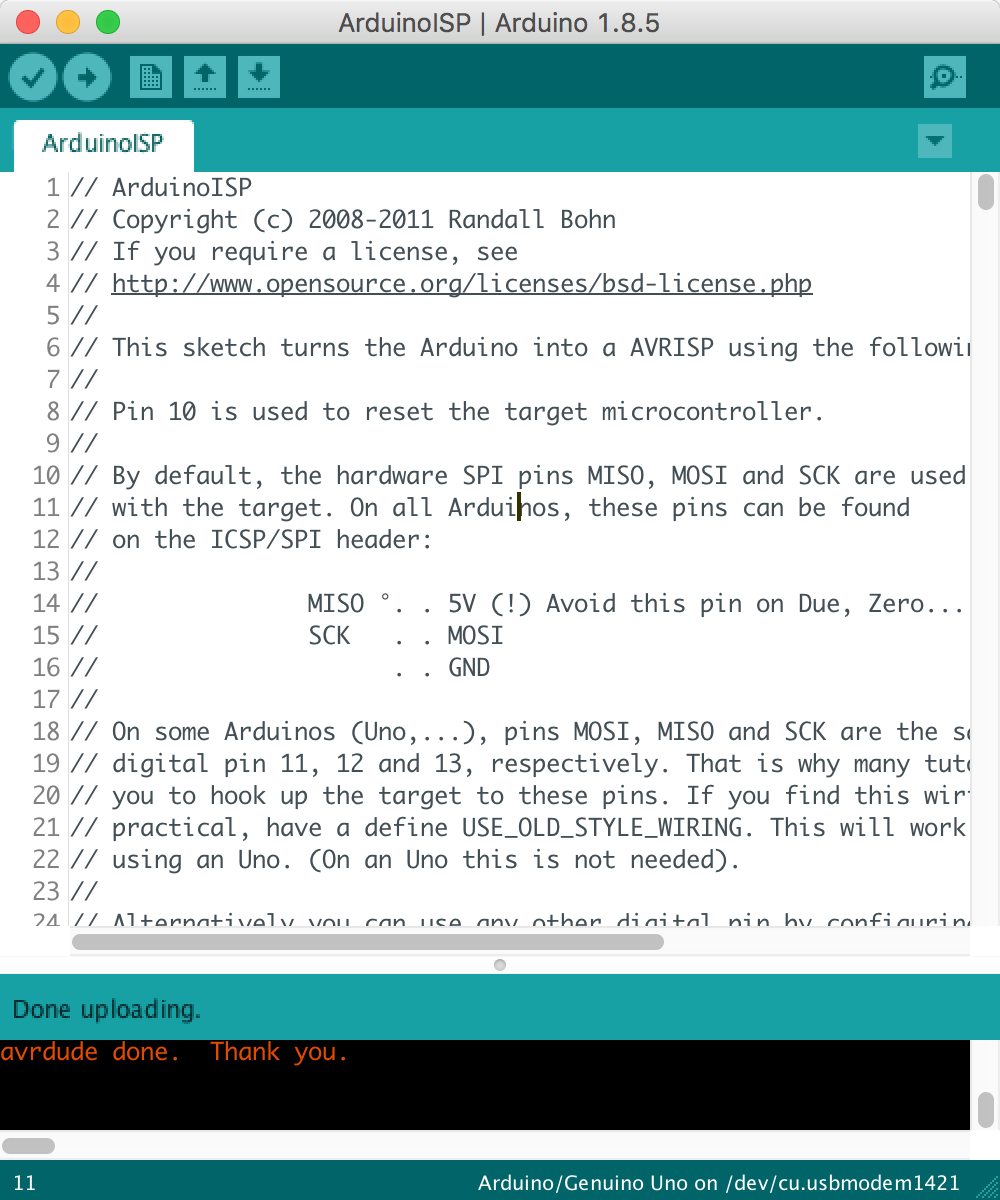
Finally, you can upload the ArduinoISP sketch to the Arduino UNO.
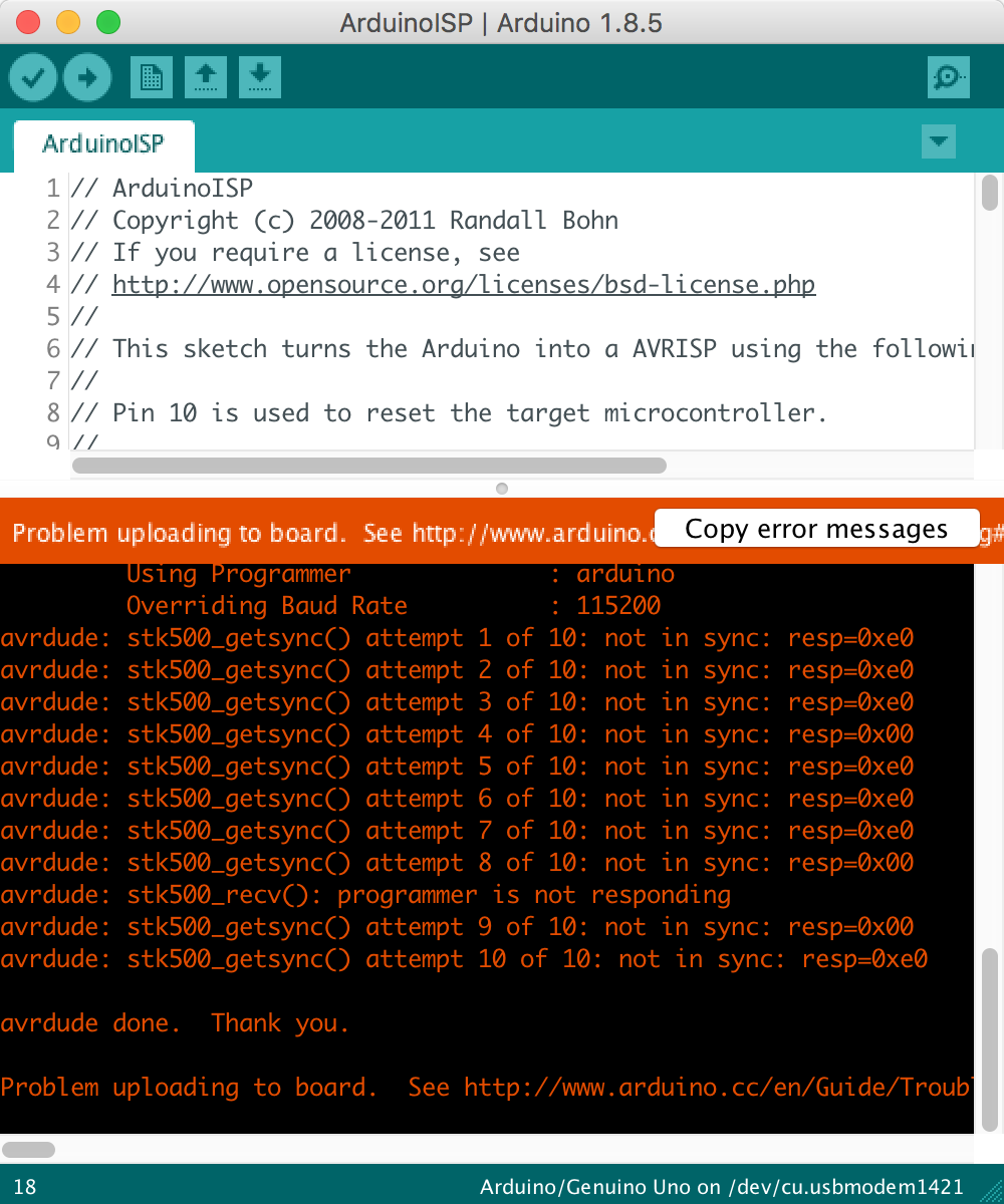
Make sure you do NOT have a capacitor connected across the RESET and GND pins on the Arduino UNO. It will prevent the Arduino UNO from resetting and thus cause the Arduino UNO to be unable to be unprogrammable.
You may get a skt500_getsync() error message which is characteristic of the capacitor across the RESET and GND problem or the settings listed above are not set properly.
If uploading the code was successful, you will get the typical Done Uploading message.
Now the Arduino UNO is configured and is ready to program AVR microcontrollers.
Sparkfun's Pocket AVR Programmer is a really easy and convenient tool to program several different AVR microcontrollers. It can even program the Arduino UNO - which is itself an ATMEGA328p.
You may have seen some familiar header pins on several devices such as the Arduino UNO:
A closer look at the pinout diagram reveals many interesting labels for each of the pins. We will not cover each of these explicitly, instead we are going to focus on the ones that are of particular importance for programming AVR microcontrollers. These pins are the Serial Peripheral Interface (SPI). SPI is a synchronized data protocol used by microcontrollers to communicate with one another over short (physical) distances. In an SPI connection, there is always one Master (e.g. Arduino UNO) that will control (or program in our case) peripheral devices, namely the target AVR microcontroller.
The SPI pins are named and labeled as follows:
We highlight one of the two SPI (Serial Peripheral Interface) headers. This one is for bootloading and programming the ATMEGA328p. The other header (next to pin 13) is to program the ATMEGA16.
Normally when we program AVR microcontrollers such as the Arduino UNO, we use a USB cable. This uses the hardware serial UART to upload our program. In the case of the Arduino UNO, the ATMEGA328 provides the means by which the USB port on your computer is able to communicate with the microcontroller. There is a solution using a Sparkfun FTDI Breakout which provides the same functionality as the ATMEGA328 on the Arduino UNO. The difference is that the programmer is external, and in general more convenient.
With AVR microcontrollers that are able to use the Sparkfun FTDI Breakout, that will be the main form of programming. For AVR microcontrollers that do not have a dedicated hardware UART (e.g. most ATtinys), then we will use the Sparkfun Pocket AVR Programmer as the main method of programming the microcontroller.
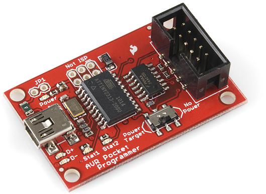
The Sparkfun Pocket AVR Programmer is as follows (without the programming cable):
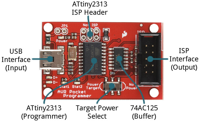
The components that make up the breakout is as follows:
list_heading
Toggling the Target Power Select will always deliver 5V. If your system is working at a voltage < 5V, it can damage or destroy your system. In this case, it is recommended you do not power the device with the Pocket AVR Programmer and instead power your device externally.
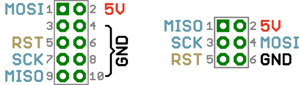
The AVR ISP pinout is the same as the Arduino UNO and many other AVR based devices:
The 2x3 header is the most common ISP header.
These are the familiar SPI pins that are required for communication between ISP (e.g. an Arduino UNO configured as an ISP, or the Pocket AVR Programmer) and AVR microcontroller (e.g. ATtiny variants, ATMEGA variants, etc.).
To use the Pocket AVR Programmer we need to prepare the AVR Pocket Programmer.
If you are using a Mac or Linux computer, you are in luck, you should not have to make any configurations or install any drivers.
If you are using a Windows computer, you may need to perform the following instructions to check if your computer can detect the Pocket AVR Programmer and install the required driver if necessary.
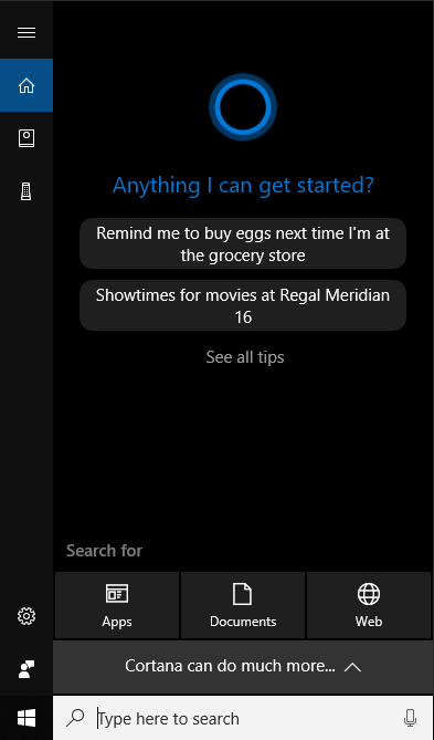
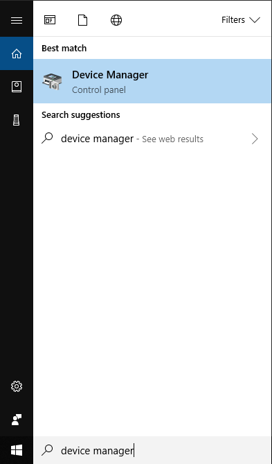
Click on the Windows key or click on the Windows icon on the task bar.
In the search bar type the following: Device Manager
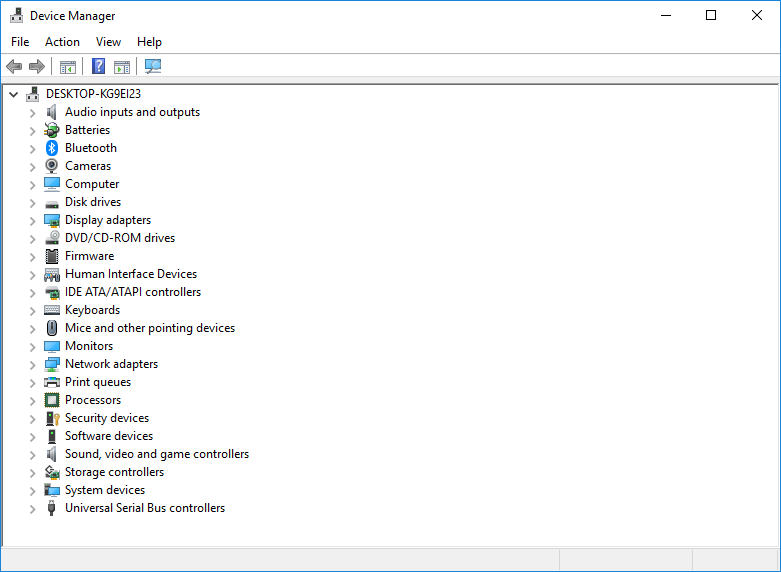
Selecting the top result for the Control Panel Device Manager opens the following window:
Plug in the Pocket AVR Programmer into one of your computer's USB ports.
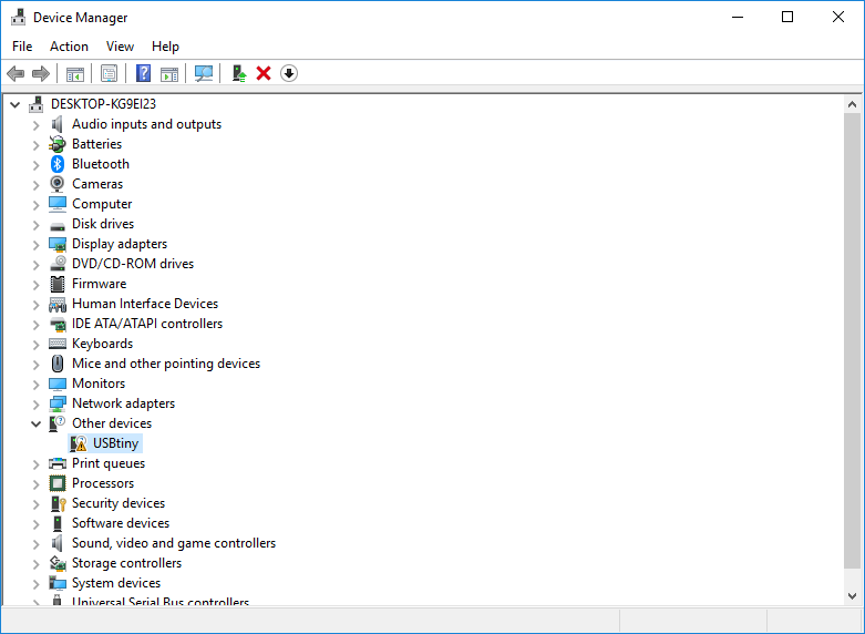
The device manager should refresh and one of the two following cases should be present:
If you get the result on the right, then you are probably good to go and the driver is already intalled and may skip the rest of this section.
On the other hand, if you get the result on the left, then you need to follow the remaining instructions to install the driver for your Windows computer to recognize the Pocket AVR Programmer.
Click the following link to download the Windows USBtinyISP signed driver provided by Adafruit Industries.
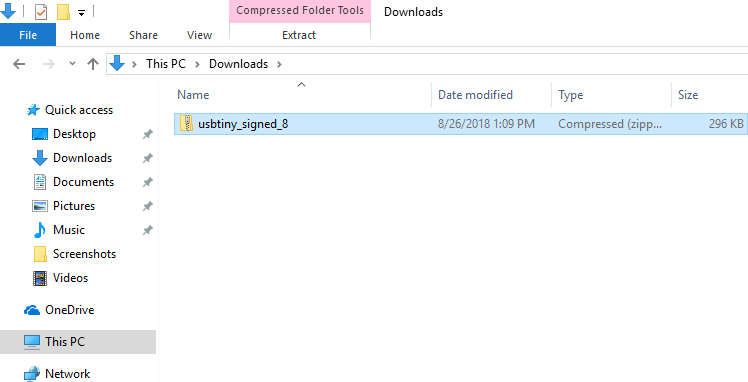
After downloading the driver, open the File Explorer and navigate to your Downloads folder or wherever you downloaded the driver to.
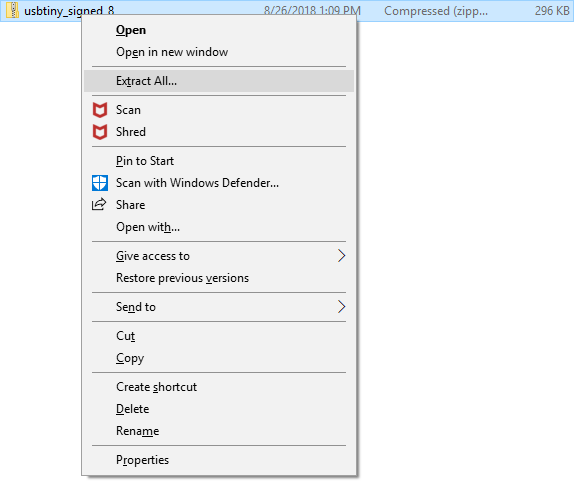
Right-click on the usbtiny_signed_8.zip file and click on Extract All....
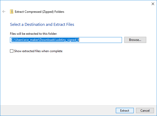
This opens the following window:
Keep the default settings and click on Extract.
Feel free to uncheck the Show extracted files when complete since we will not be exploring the extracted folder contents.
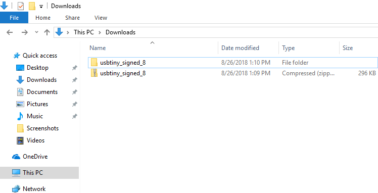
This will extract the .zip file into a folder with the identical name in the same directory as shown:
Click on the Windows key or click on the Windows icon on the task bar.
In the search bar type the following: Device Manager
Selecting the top result for the Control Panel Device Manager opens the following window:
Plug the Pocket AVR Programmer into one of your computer's USB ports.
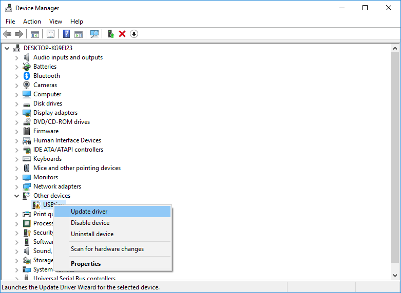
The device manager should refresh and the following should be present:
Right click on the USBtiny device with the yellow exclamation point.
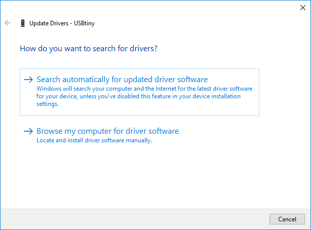
Click on Update driver which will open the following window:
Click on Browse my computer for driver software.
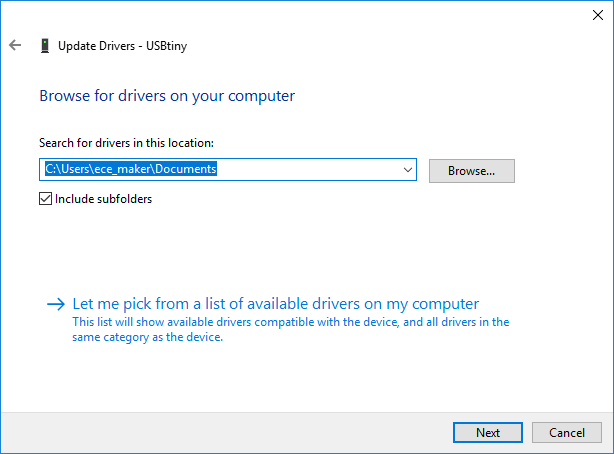
The next screen should appear as follows:
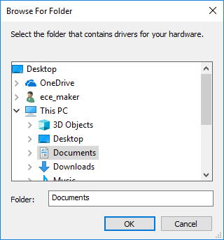
The search for drivers in this location path is not pointing to our extracted drivers. Click on Browse... to open the following window (left).
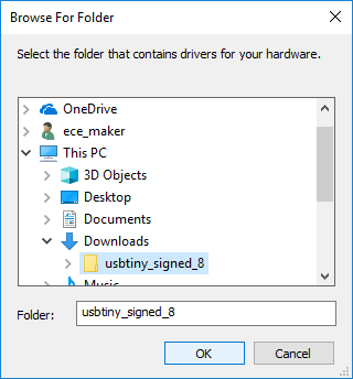
Navigate to find the usb_signed_8 folder we extracted (in Downloads or wherever you downloaded and extracted the driver) (right).
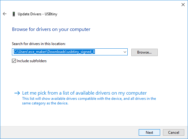
Once you navigate to the appropriate directory, click OK to return to the previous window with the correct path.
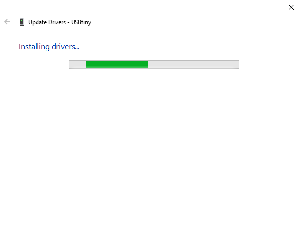
Click Next to begin the installation.
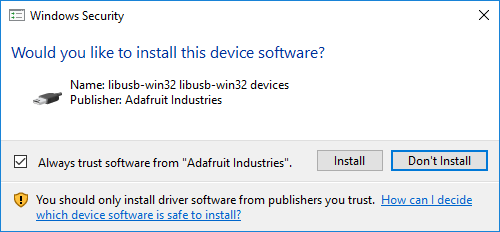
You may receive the following Windows Security flag:
Click Install to permit, continue, and complete the installation.
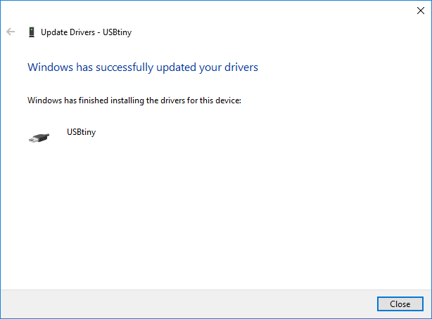
When the installation completes, click Close to close the window.
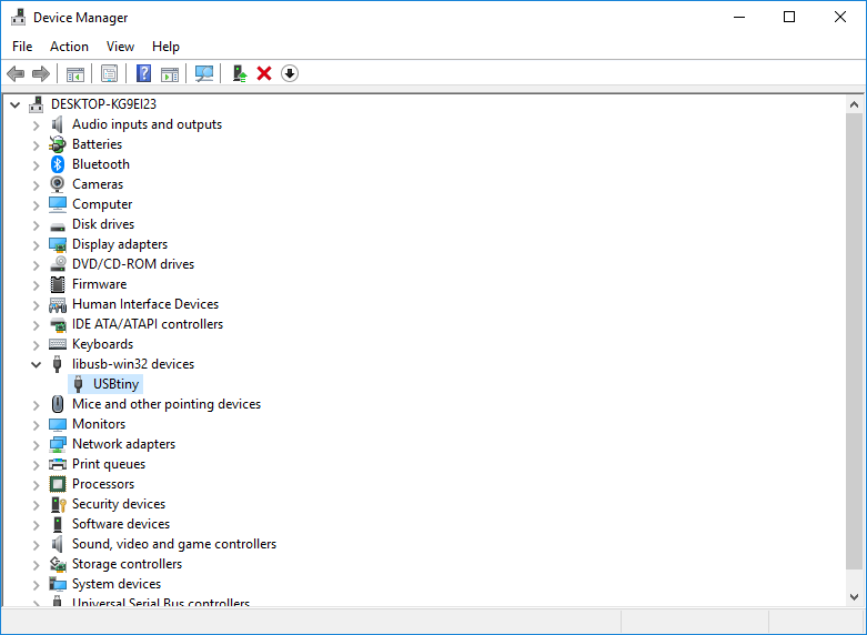
The Device Manager window should refresh and even with the Pocket AVR Programmer, the missing device driver should disappear.
A new device category should appear called libusb-win32 devices. Expanding this category should reveal USBtiny.
The driver is successfully installed and you should be good to go with the Pocket AVR Programmer.
Now we will discuss the remaining general settings for programming the AVR microcontrollers with your configured AVR microcontroller programming device.
Port refers to the particular USB port on your computer the hardware is connected to.
Set Port to be the port your Arduino UNO is connected to.
Port names are variable across different operating systems (Windows, Mac OS, and Linux) and physical USB ports.
When using the Pocket AVR Programmer, there is no port that will appear when the Pocket AVR Programmer is plugged into your computer.
You do NOT have to choose a port. The way we upload programs to the AVR microcontroller using the Pocket AVR Programmer is slightly different and does not depend on a particular port.
The Port setting is configured to program the AVR Microcontroller.
The Programmer is important, and is subtle – easy to forget when programming these MCUs. This tells the Arduino IDE how to behave when uploading your program (to the Arduino UNO, ATtiny, etc.).
When we uploaded the ArduinoISP sketch to Arduino UNO earlier, we set Programmer to AVRISP mkII so that when we uploaded the code it targeted the Arudino UNO. However, now we want to target the AVR microcontroller and have the Arduino UNO behave as an ISP (In-System Programmer) instead.
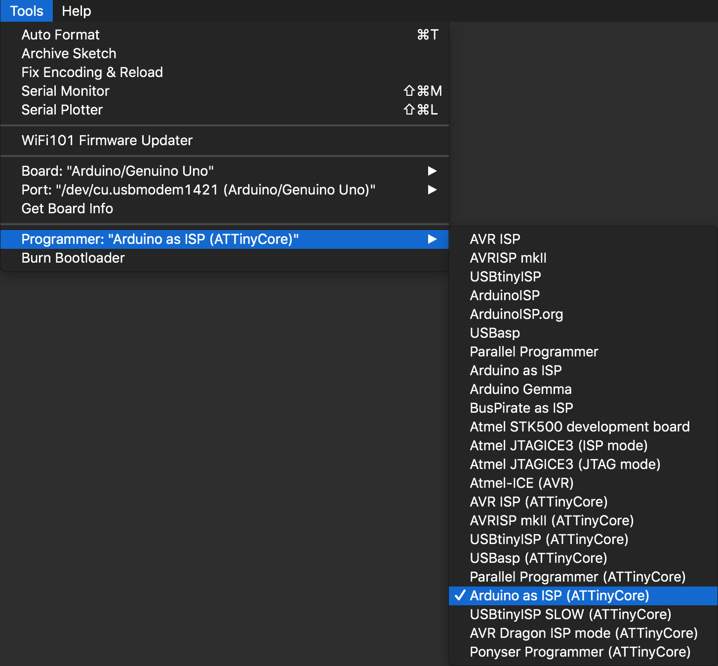
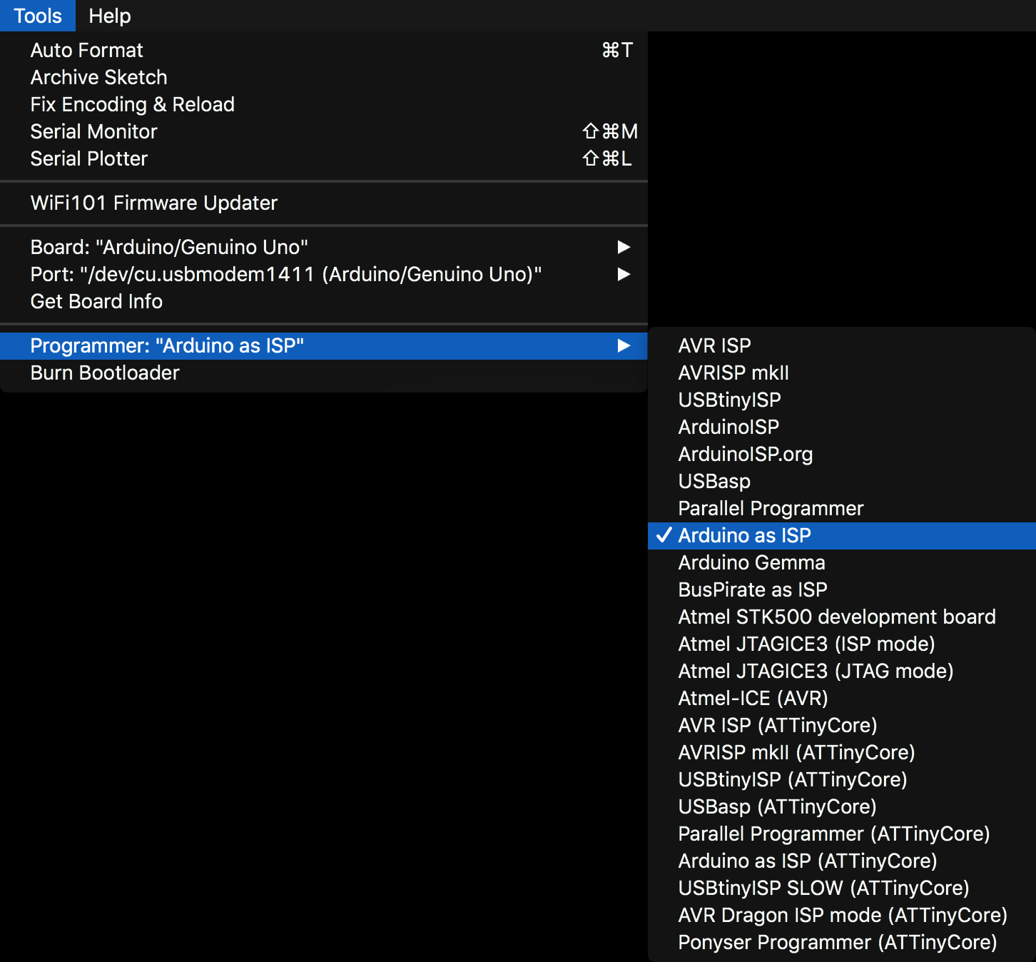
To program any of the AVR microcontroller variants, we set the Programmer setting to Arduino as ISP (ATtinyCore) for ATtiny variants and Arduino as ISP for ATMEGA variants. Where ISP stands for In-System Programmer. This effectively tells the Arduino UNO to pass or forward the code to the target AVR microcontroller instead of programming the Arduino UNO itself. Thus, we will be using the Arduino UNO as the middle-man to program the AVR microcontroller variants.
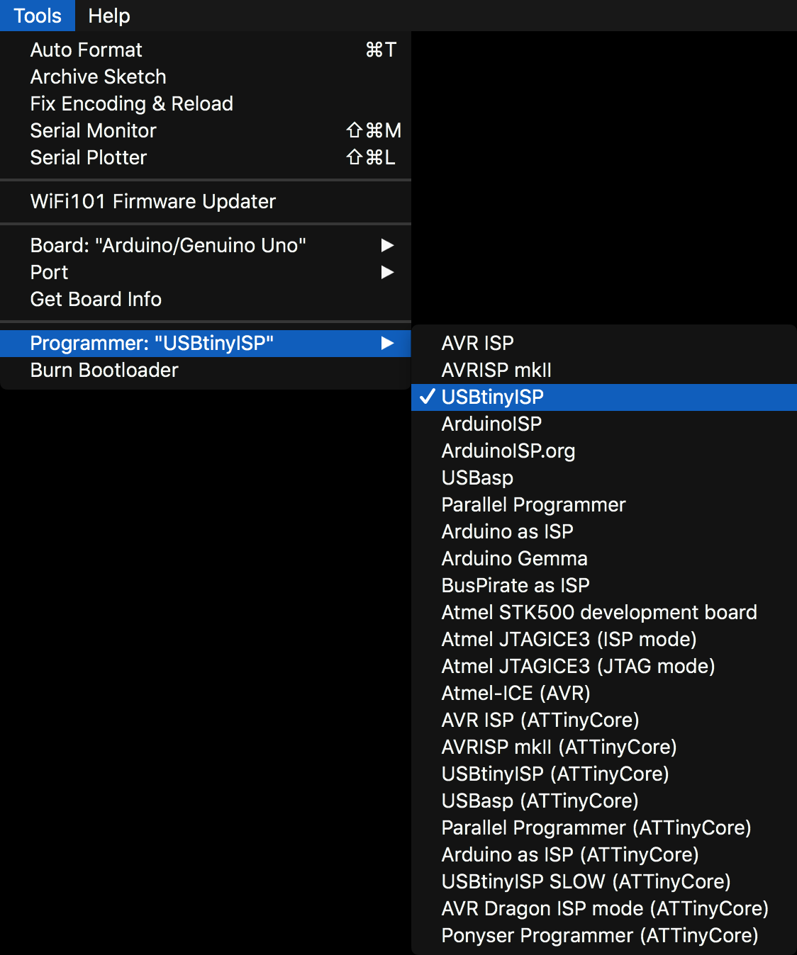
To program any of AVR microcontroller variants using the Pocket AVR Programmer, we set the Programmer setting to USBtinyISP. Where ISP stands for In-System Programmer, we are using a USB cable, and tiny refers that the Pocket AVR Programmer uses an ATtiny microcontroller (an ATtiny2313 to be specific). The Pocket AVR Programmer effectively translates the USB signals to SPI signals to program the AVR microcontroller target.
The Programmer setting is configured to program the AVR Microcontroller.
Burning the bootlaoder process is identical for both the Arduino UNO configured as an ISP and using the Pocket AVR Programmer.
Burn Bootloader is the most important setting and the easiest setting to forget. The Burn Bootloader is not a selectable option. Selecting this option will immediately attempt to burn the bootloader to your device (Arduino UNO, AVR microcontroller variant, etc.).
This will take all the applicable configured settings we have done prior to this (i.e. Save EEPROM, LTO, B.O.D., and Clock) and burn/program the fuses bits of the microcontroller for the selected Chip setting. The fuses are essentially a special memory space in the device for the aforementioned settings.
Burning the Bootloader is identical for any method when programming an AVR microcontroller.
Selecting Burn Bootloader will act instantly!
You should always Burn Bootloader when first using the AVR microcontroller variant chip. You never know what fuse settings came with the board by default.
Be sure all the settings we have discussed during this tutorial are set appropriately.
For the Clock setting, if you do external on accident, you will brick (effectively disable or render useless) the AVR microcontroller until you connect the corresponding external clock. Do NOT select any external clock rates unless you already have an external oscillator configured.
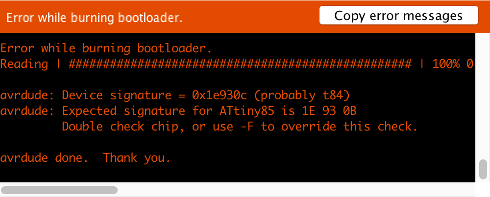
When initiating Burn Bootloader, you may receive an error message similar following:
This error means that the AVR microcontroller you are programming cannot be identified correctly (by its unique signature). This occurs if your physical connections are incorrectly wired. It can also occur if the Board, or Chip, settings are incorrect.
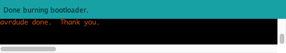
For a successful Burn Bootloader, you will get a familiar success message:
With Burn Bootloader completed, we are ready to program AVR Microcontrollers! We can now upload typical Arduino sketches. Just remember when programming the AVR microcontroller, we have set all the appropriate settings and be aware of some of the limitations of some AVR Microcontrollers and - most notably - AVR microcontroller.
We have outlined bootloading most AVR microcontrollers in general.
In general, ATtinys do not have a hardware UART, the same configuration for bootloading is used to explicitly program an ATtiny with a typical Arduino sketch.
On the other hand, in general, ATMEGAs do have a dedicated hardware UART, and although one could use the same configuration for bootloading to explicitly program an ATMEGA, it is common practice to use the hardware UART (serial TX and RX pins) to program ATMEGA variants. This uses another piece of hardware: Sparkfun FTDI Breakout. It may seem like another piece of hardware to buy - and yes, to some degree this is true. However, in custom PCBs it is common to integrate the contents of the Sparkfun FTDI Breakout onto the PCB, so all you need is a USB cable - just like you would with the Arduino UNO!
Although we have not explicitly given examples of programming AVR microcontroller here, we have the ATtiny and ATMEGA tutorials where we go in depth explicitly configuring the hardware to program a few popular (and cheap) AVR microcontrollers as well as several other projects in our Related Projects at the bottom of the page.
Here we have covered the installation process for the AVR microcontroller boards into the Arduino IDE. This is one of a few ways to install 3rd party “boards” (i.e. development boards, microcontroller chips, etc.) into your Arduino IDE so you can write programs using the Arduino IDE and upload them directly to your board.
The Arduino UNO is a great development board for prototyping and a great place to start for the price. However, the Arduino UNO cannot do everything. It has limitations. There are several other development boards out there that can do more than the Arduino UNO that each have their advantages and disadvantages, and some that are specialized. There are also cases when you may not be using the Arduino UNO to its full potential and ATtinys are great microcontrollers that are perfect when the Arduino UNO (i.e. ATMEGA328p) is over-specificied.
Thus, for your project and its application, it is wise to consider different development boards or even programming a microcontroller chip directly. Being aware of this powerful concept and why we are investigating the various AVR microcontroller variants, installing new boards, and playing with new technologies!