Getting started with the ATtinyX4 microcontroller.
Designed by:
Colin "MrSwirlyEyes" Keef
ATtiny AVR microcontrollers are awesome programmable chips that are great for simple stand alone projects. There have been several occasions where we found ourselves making a project with an Arduino UNO where we only utilized a small subset of the total number of IO pins. The entire Arduino UNO development board at our disposal, and we use only a fraction of its potential. Furthermore, the Arduino UNO costs approximately $25 and its microcontroller the ATMEGA328p costs approximately $2. If we are only using a subset of pins, we can have a smaller footprint and reduced price using an ATtinyX4 microcontroller. You can still program this microcontroller in the Arduino IDE. Granted there are some disadvantages, not having a dedicated hardware UART and the inability to use some of the same libraries the ATMGEA328p is capable of, it can still find its niche in some simple projects.
In this tutorial, we explore the ATtinyX4 and get you started playing with the ATtiny84. At the end of the tutorial you can find other related projects and tutorials that utilize AVR microcontrollers and we encourage you to try and port your next project to an ATtinyX4!
| DEVICE | VENDOR URL | QUANTITY | NOTES |
|---|---|---|---|
| Arduino UNO R3 | Digikey | 2 | May use other variants, but may need minor changes to code. |
| USB Cable (A Male to B Male) | Digikey | 2 | |
| ATtiny84 MCU IC 8BIT 8KB FLASH 8DIP | Digikey | 1 | May substitute for any other ATtinyX4 module. |
| LED BLUE CLEAR T-1 3/4 T/H | Digikey | 10 | Can substitute for any desired color LED. |
| RES 10K OHM 1/4W 5% AXIAL | Digikey | 10 | Can substitute for appropriate sized resistor(s). |
| CAP ALUM 10UF 20% 50V RADIAL | Digikey | 1 | Aluminum Electrolytic Capacitor (polarized). Any similar value will work too. Any similar value will work too. Any similar value will work too. Any similar value will work too. Any similar value will work too. Any similar value will work too. Any similar value will work too. Any similar value will work too. Any similar value will work too. Any similar value will work too. Any similar value will work too. Any similar value will work too. Any similar value will work too. Any similar value will work too. Any similar value will work too. Any similar value will work too. Any similar value will work too. Any similar value will work too. Any similar value will work too. Any similar value will work too. Any similar value will work too. Any similar value will work too. Any similar value will work too. Any similar value will work too. Any similar value will work too. Any similar value will work too. Any similar value will work too. Any similar value will work too. Any similar value will work too. Any similar value will work too. Any similar value will work too. Any similar value will work too. Any similar value will work too. Any similar value will work too. Any similar value will work too. Any similar value will work too. Any similar value will work too. Any similar value will work too. Any similar value will work too. Any similar value will work too. Any similar value will work too. Any similar value will work too. Any similar value will work too. Any similar value will work too. Any similar value will work too. Any similar value will work too. Any similar value will work too. Any similar value will work too. Any similar value will work too. Any similar value will work too. Any similar value will work too. Any similar value will work too. Any similar value will work too. Any similar value will work too. Any similar value will work too. Any similar value will work too. Any similar value will work too. Any similar value will work too. Any similar value will work too. Any similar value will work too. Any similar value will work too. Any similar value will work too. Any similar value will work too. Any similar value will work too. Any similar value will work too. Any similar value will work too. Any similar value will work too. Any similar value will work too. Any similar value will work too. Any similar value will work too. Any similar value will work too. Any similar value will work too. Any similar value will work too. Any similar value will work too. Any similar value will work too. Any similar value will work too. Any similar value will work too. Any similar value will work too. Any similar value will work too. Any similar value will work too. Any similar value will work too. Any similar value will work too. Any similar value will work too. Any similar value will work too. Any similar value will work too. Any similar value will work too. Any similar value will work too. Any similar value will work too. Any similar value will work too. Any similar value will work too. Any similar value will work too. Any similar value will work too. Any similar value will work too. Any similar value will work too. Any similar value will work too. Any similar value will work too. Any similar value will work too. Any similar value will work too. Any similar value will work too. Any similar value will work too. Any similar value will work too. Any similar value will work too. Any similar value will work too. Any similar value will work too. Any similar value will work too. Any similar value will work too. Any similar value will work too. Any similar value will work too. Any similar value will work too. Any similar value will work too. Any similar value will work too. Any similar value will work too. Any similar value will work too. Any similar value will work too. Any similar value will work too. Any similar value will work too. Any similar value will work too. Any similar value will work too. Any similar value will work too. Any similar value will work too. Any similar value will work too. Any similar value will work too. Any similar value will work too. Any similar value will work too. Any similar value will work too. Any similar value will work too. Any similar value will work too. Any similar value will work too. Any similar value will work too. Any similar value will work too. Any similar value will work too. Any similar value will work too. Any similar value will work too. Any similar value will work too. Any similar value will work too. Any similar value will work too. Any similar value will work too. Any similar value will work too. Any similar value will work too. Any similar value will work too. Any similar value will work too. Any similar value will work too. Any similar value will work too. Any similar value will work too. Any similar value will work too. Any similar value will work too. Any similar value will work too. Any similar value will work too. Any similar value will work too. Any similar value will work too. Any similar value will work too. Any similar value will work too. Any similar value will work too. Any similar value will work too. Any similar value will work too. Any similar value will work too. Any similar value will work too. Any similar value will work too. Any similar value will work too. Any similar value will work too. Any similar value will work too. Any similar value will work too. Any similar value will work too. Any similar value will work too. Any similar value will work too. Any similar value will work too. Any similar value will work too. Any similar value will work too. Any similar value will work too. Any similar value will work too. Any similar value will work too. Any similar value will work too. Any similar value will work too. Any similar value will work too. Any similar value will work too. |
| Breadboard (small) | Digikey | 2 | Used for prototyping. |
| Jumper Wire M/M 6 (20pcs) | Digikey | 2 | Used for prototyping. |
| [Optional] POCKET AVR PROGRAMMER | Digikey | 1 | Optional if using Arduino UNO as ISP. Used to bootload AVR microcontrollers. |
| [Optional] USB Cable (A Male to Mini B Male) | Digikey | 1 | Accessory to AVR Pocket Programmer. |
In this module, we introduce you to ATtiny AVR microcontrollers in general. Most of them operate largely the same including their set up, configuration, and programming them.
Most AVR microcontrollers behave the same where they are an ATtiny variant or ATMEGA variant. We have a tutorial that introduces AVR microcontrollers and what is necessary to get started using them. Pay close attention to this tutorial as we describe how to work with AVR microcontrollers in general. You need to decide whether you would like to use an Arduino UNO as an ISP to program your ATtinyX4, or the Sparkfun Pocket AVR Programmer. The tutorial covers AVR microcontrollers and is mostly split up between ATtiny AVR microcontrollers and ATMEGA AVR microcontrollers - we want to follow the ATtiny specfic parts! After you go through the tutorial, return here and we will dive specifically into the ATtinyX4. Now, we direct you to the tutorial here: AVR Microcontrollers
Returning from the AVR Microcontrollers tutorial. We should have the ATtinyCore installed, know what device we will use to bootload and program the ATtinyX4 (Arduino as ISP or Pocket AVR Programmer), have some familiarity of the board settings (we will explore the ATtinyX4 settings explicitly), and some of the bootloading process (again, explicitly covered here).
In the next module, we explore the ATtinyX4.
Now we focus on the ATtinyX4 microcontroller explicitly. We will cover its pinout, capabilities and explore the process for which we program the ATtinyX4 in detail.
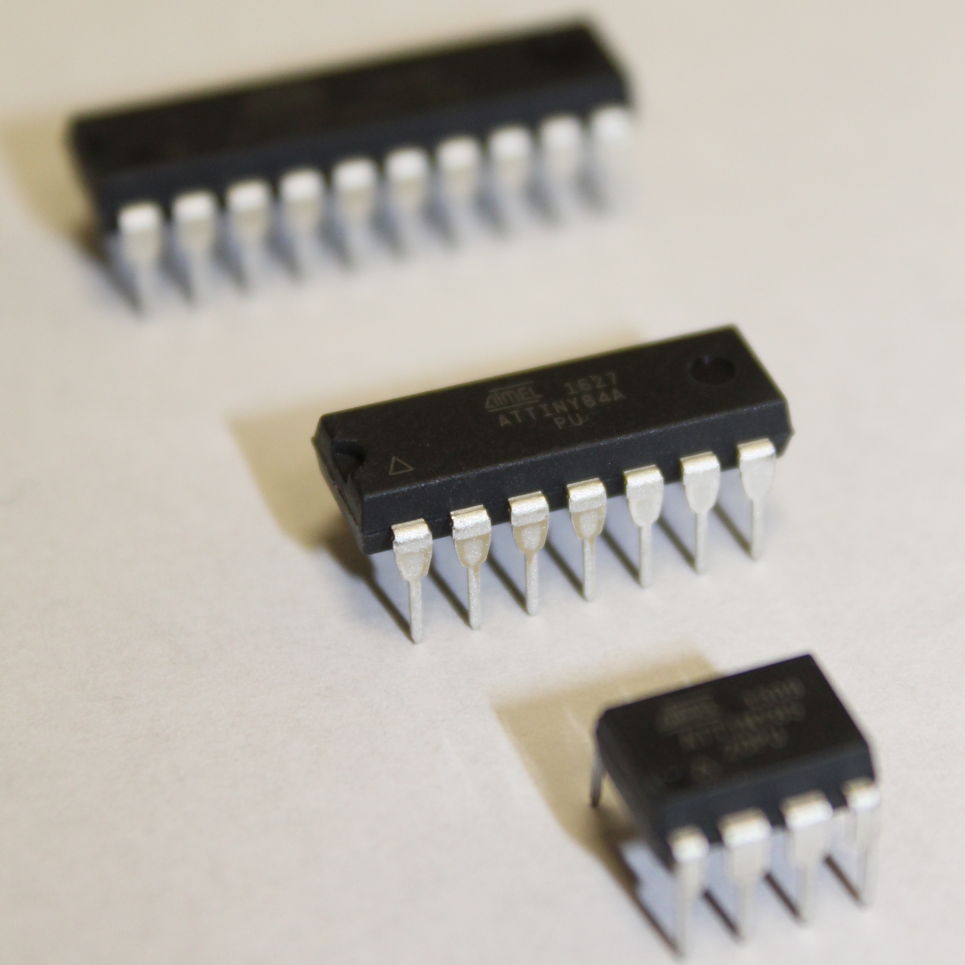
We refer to the ATtinyX4 where the 'X' can be either 2, 4, or 8. Thus, there are three different variants of the ATtinyX4, namely: ATtiny24, ATtiny44, and ATtiny84. They are all identical except for how much flash memory, RAM (Random Access Memory), and EEPROM (Electrically Erasable Programmable Read-Only Memory). This is shown in the specifications table below.
The specifcations of the ATtinyX4 variants are outlined as follows:
| Specifications | |
|---|---|
| Flash (program memory) | 2048/4096/8192 bytes |
| RAM (Random Access Memory) | 128/256/512 bytes |
| EEPROM (Electrically Erasable Programmable Read-Only Memory) | 128/256/512 bytes |
| Bootloader | no |
| GPIO pins | 12 |
| ADC (Analog-to-Digital Converter) Channels | 12 (including the one on RESET) |
| PWM (Pulse-Width Modulation) Channels | 4 |
| Interfaces | USI |
| Clock options | internal 1/8 MHz, external crystal or clock up to 20 MHz |
The following shows the pinout diagram for the ATtinyX4:
The pins of interest are the following:
In-System Programmer (ISP) Pins paralleled with that of those on the Arduino UNO (or ATMEGA328p):
Unlike the Arduino UNO which has a SS (Slave Select) pin. The ATtiny does not have one. Instead, we will need to use the RESET pin since the ATtiny will be the slave device.
Note that, for the ATtiny84, there are two pin mappings. One has an increasing (digital) pin count in the clockwise direction, and the other (labeled alternative pinout has an increasing (digital) pin count in the counterclockwise direction. According to SpencerKonde's ATtinyCore, they are named as follows:
Both are valid pinouts and one has to be selected when bootloading the ATtinyX4.
You can choose either and be sure to refer to the appropriate pin mapping as shown in the ATtiny84 pinout:
Even for such a small chip, there is a ton of information that we are not able to cover. Feel free to checkout the complete documentation of the ATtinyX4 from its datasheet linked in the Resources and References at the bottom of the page.
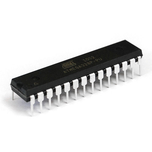
Observe the similarities of the ATtinyX4 to the Arduino UNO (or ATMEGA328p), shown below for reference:
Now that we have familiarized with the ATtinyX4, we are ready to bootload and program the microcontroller now!
In this module, we will walk through the process in which we bootload the ATtinyX4. Bootloading AVR microcontrollers is an essential step to ensure that the microcontroller behaves appropriately. In AVR microcontrollers that do not have a hardware UART, the same method to bootload the microcontroller is employed to program the microcontroller.
To bootload the ATtinyX4, we need to use an external master device to program our ATtinyX4 (slave device). There are several ways we can do this. The most common way is to use an Arduino UNO to program the ATtinyX4. This is usually easy because it is assumed that you already have an Arduino UNO on hand. Another common method is to use Sparkfun's Pocket AVR Programmer.
From the AVR Microcontrollers tutorial, configure your Arduino IDE and/or programming device. Assuming the ATtiny board settings in the Arduino IDE are configured appropriately.
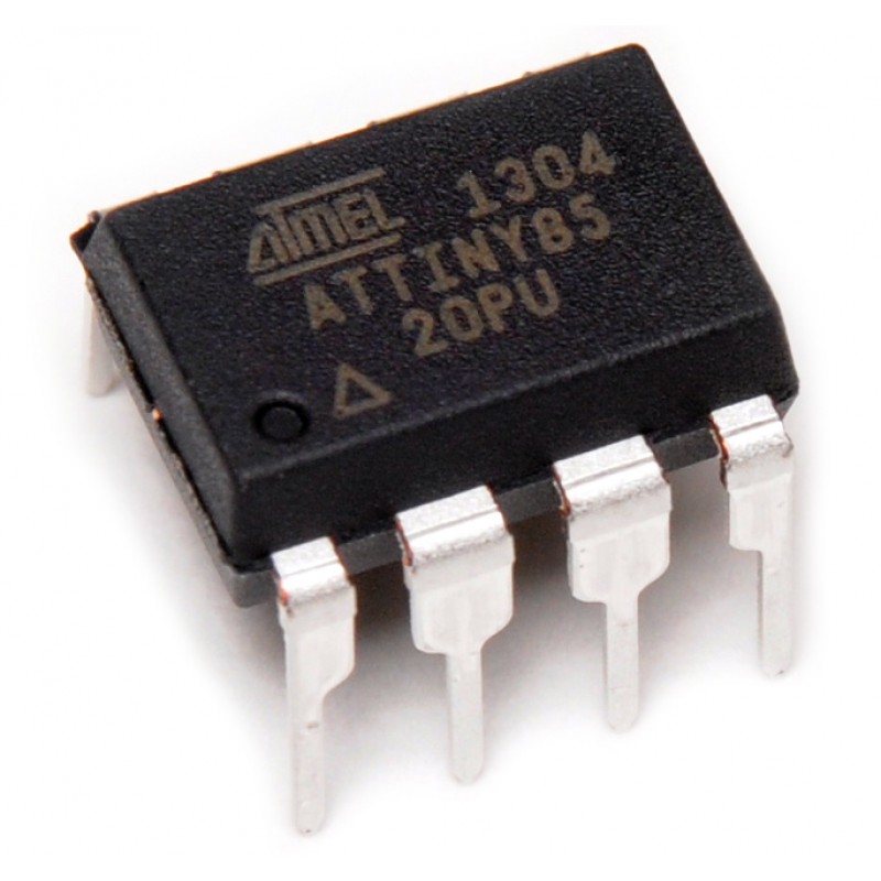
From hereon out, we will be using at ATtiny84 to demonstrate the bootloading process. We will still mention ATtinyX4 where it is general, but configure the appropriate settings for the ATtiny84. However, this same process can be applied to any of the ATtinyX4 variants, given that you make the appropriate change at the Chip selection shown later.
Next, we have to burn the bootloader to the ATtinyX4.
If you have not done so yet, make sure your Arduino UNO is configured as an In-System Programmer, which is outlined in the Bootloading AVR Microcontrollers module in the AVR Microcontrollers tutorial.
With your Arduino UNO configured, we need to build the following circuit to connect the Arduino UNO to the ATtinyX4:
Pay close attention to the schematic. The ATtinyX4 physical pins (numbers protruding from the symbol) and Arduino or programming pins (in the description inside the symbol) are labeled on the schematic.
The 10µF capacitor prevents the Arduino UNO from automatically resetting when we bootloading/programming the ATtinyX4.
Observe that the Serial pins of the Arduino UNO are connected to the ISP pins of the ATtinyX4. Furthermore, the ATtinyX4 needs to be powered when we bootload/program it, we can just tap off the Arduino UNO power rail pins with it connected to your computer USB port. We outline these connections in the following table:
| Arduino UNO (physical pin) | ATtinyX4 (physical pin) |
|---|---|
| 3.3V or 5V | VCC (pin 1) |
| SCK (pin 13) | SCK (pin 9) |
| MISO (pin 12) | MISO (pin 8) |
| MOSI (pin 11) | MOSI (pin 7) |
| SS (pin 10) | RESET (pin 4) |
| GND | GND (pin 14) |
Do not confuse the physical pin with the Arduino or programming pin.
Although the schematic shows the connection to 3.3V, 5V will also work just as well.
Please use the Chip Remover when removing ATtiny microchips, the pins are extremely fragile. If you break a pin, the chip practically becomes useless.
With the appropriate settings selected in the Arduino IDE, first select Burn Bootloader to burn the selected settings to the ATtinyX4.
Remember to pick the appropriate Pin Mapping!
Be sure you have selected Arduino as ISP (ATtinyCore) for the programmer setting. As for clock, we recommend using the default 8 MHz crystal - do NOT select an external clock unless you know what you are doing.
To burn the bootloader, on the Arduino IDE navigate to Tools and click Burn Bootloader.
Selecting Burn Bootloader will act instantly!
You should always Burn Bootloader when first using the ATtiny variant chip. You never know what fuse settings came with the board by default.
Be sure all the settings we have discussed during this tutorial are set appropriately.
For the Clock setting, if you do external on accident, you will brick (effectively disable or render useless) the ATtiny until we connect the corresponding external clock. Do NOT select any external clock rates unless you already have an external oscillator configured.
If your connections are correct, you should receive a successful Burn Bootloader message.
If you do NOT get a successful Burn Bootloader message, please check your circuit, the board settings, and make sure the ArduinoISP sketch has been uploaded to your Arduino UNO.
If you have not done so yet, make sure you have the Pocket AVR Programmer configured appropriately, which is outlined in the Bootloading AVR Microcontrollers module in the AVR Microcontrollers tutorial.
With your Pocket AVR Programmer configured, we need to build the following circuit to connect the Pocket AVR Programmer 2x3 ISP header to the ATtiny:
You need to use your imagination (since we do not have a physical picture here - only a schematic representation). The Pocket AVR Programmer 2x3 ISP header has a key sticking out of one end of the connector (which is illustrated in the schematic). This is also from a top-view perspective.
Pay close attention to the schematic. The ATtinyX4 physical pins (numbers protruding from the symbol) and Arduino or programming pins (in the description inside the symbol) are labeled on the schematic.
Observe that the Serial pins of the Pocket AVR Programmer are connected to the ISP pins of the ATtinyX4. Furthermore, the ATtinyX4 needs to be powered when we program it, we can just tap off an Arduino UNO power rail pins with it connected to your computer USB port or using the Pocket AVR Programmer itself by toggling the switch between Power Target and No power.
Careful if you chose to power the ATtinyX4 using the Pocket AVR Programmer, it provides 5V when Power Target is selected. This is convenient for breadboard prototyping in general, however it is common to not to use the Pocket AVR Programmer to power the target (e.g. ATtiny) when it is on its own (custom) PCB because you may be using a voltage less than 5V which may damage your custom circuitry.
We outline these connections in the following table:
| Pocket AVR Programmer (2x3 ISP header) |
ATtinyX4 (physical pin) |
|---|---|
| 5V (pin 2) or NC | VCC (pin 1) |
| SCK (pin 3) | SCK (pin 9) |
| MISO (pin 1) | MISO (pin 8) |
| MOSI (pin 4) | MOSI (pin 7) |
| RESET (pin 5) | RESET (pin 4) |
| GND (pin 6) | GND (pin 14) |
Do not confuse the physical pin with the Arduino or programming pin for the ATtiny.
The connection to the Pocket AVR Programmer VCC (5V) pin may NOT need to be connected if you will power your microcontroller with an external power source.
Please use the Chip Remover when removing ATtiny microchips, the pins are extremely fragile. If you break a pin, the chip practically becomes useless.
With the appropriate settings selected in the Arduino IDE, first select Burn Bootloader to burn the selected settings to the ATtiny84.
Remember the Pocket AVR Programmer will NOT show up in Port, so it is OK to have nothing selected.
Remember to pick the appropriate Pin Mapping!
Be sure you have selected USBtinyISP for the programmer setting. As for clock, we recommend using the default 8 MHz crystal - do NOT select an external clock unless you know what you are doing.
For the ATtiny84, there are two pin mappings:
You can choose either and be sure to refer to the appropriate pin mapping as shown in the ATtiny84 pinout:
To burn the bootloader, on the Arduino IDE navigate to Tools and click Burn Bootloader.
Selecting Burn Bootloader will act instantly!
You should always Burn Bootloader when first using the ATtiny variant chip. You never know what fuse settings came with the board by default.
Be sure all the settings we have discussed during this tutorial are set appropriately.
For the Clock setting, if you select external on accident, you will brick (effectively disable or render useless) the ATtiny until we connect the corresponding external clock. Do NOT select any external clock rates unless you already have an external oscillator configured.
If your connections are correct, you should receive a successful Burn Bootloader message.
If you do NOT get a successful Burn Bootloader message, please check your circuit, and the board settings.
With the bootloader burned to your ATtinyX4, we are finally ready to program it with custom code! You will keep the same circuit configuration used for burning the bootloader to program the ATtiny with a typical Arduino sketch.
In this module, we will program the ATtinyX4. The program we upload to the ATtinyX4 is trivial, however we encourage you to explore its capabilities further in your own application!
We demonstrate a trivial example of programming the ATtinyX4, the typical blink sketch. You may now open a new sketch and write your own code or copy-paste the following code into the sketch:
// Trivial program to test the ATtinyX4.
//
// Toggles LED on and off for a fixed period of time.
//  Typical blink sketch.


#define led 5

void setup() {
  // Initialize ATtinyX4 digital physical pin 8
  //	(programming pin 5) as an output.
  pinMode(led, OUTPUT);
}

void loop() {
  // Toggle LED on
  digitalWrite(led, HIGH);
  delay(1000);

  // Toggle LED off
  digitalWrite(led, LOW);
  delay(1000);
}
With the same settings from the Burn Bootloader module, instead of burning the bootloader, upload the program to the ATtiny84 like you would with any Arduino device!
If you are using the Pocket AVR Programmer, you may have to press (CMD + SHIFT + U or CTRL + SHIFT + U) to upload using the AVR Pocket Programmer or navigate to Sketch > Upload Using Programmer for the equivalent action.
You should receive the typical successful programming message.
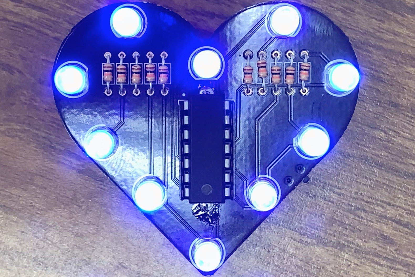
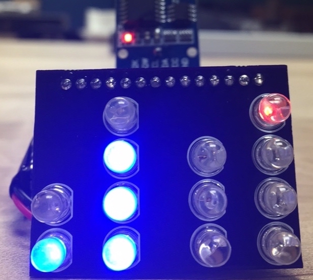
With the code given above, the ATtinyX4 will toggle one of the digital pins. The following circuit blinks an LED using the appropriate digital pin designated in the uploaded code:
The results should be similar to:
And that is it! Your ATtinyX4 should be blinking an LED. This was a trivial example, but it is the start of many possibilities to reduce your overall hardware footprint and cost. The ATtiny can do a large subset of what the Arduino UNO (ATMEGA328p) can do, so if you have an existing Arduino project that is using only a subset of pins and is relatively simple, consider whether you can free up that Arduino and use an ATtiny instead. If the ATtinyX4 does not have enough GPIO pins, there are several other ATtiny or ATMEGA variants that have more or less pins than the Arduino UNO (ATMEGA328p).
The concept of programming AVR microcontrollers is the take away from this tutorial. Prototyping using Arduino development boards is still the way to go. However, if you find yourself using a small subset of pins or want to reduce your hardware then start asking yourself if the microcontroller you are using is under (or over) specified for your completed project. The understanding of the Arduino UNO (ATMEGA328p) is not much different than ATtiny AVR microcontrollers. They are very similar. If you want to make your own custom hardware or product, then making and breaking the development board is necessary to make your own embedded project!