Program your own lightshow on a customized PCB deployed ATtiny84!
Designed by:
Colin "MrSwirlyEyes" Keef
The Heart CKT is a simple application of system on a chip design. (Also, an application of the ATtiny Programmer). We will be programming an AVR microcontroller, namely the ATtiny84, to light up 10 LEDs in a radiant lightshow.
These LEDs may be individually controlled giving the user full control when programming their lightshow. We will be able to use the Arduino IDE to do our programming, and then we can simply upload our program to the ATtiny84 using traditional methods for programming AVR microcontrollers (or, optionally, an ATtiny Programmer).
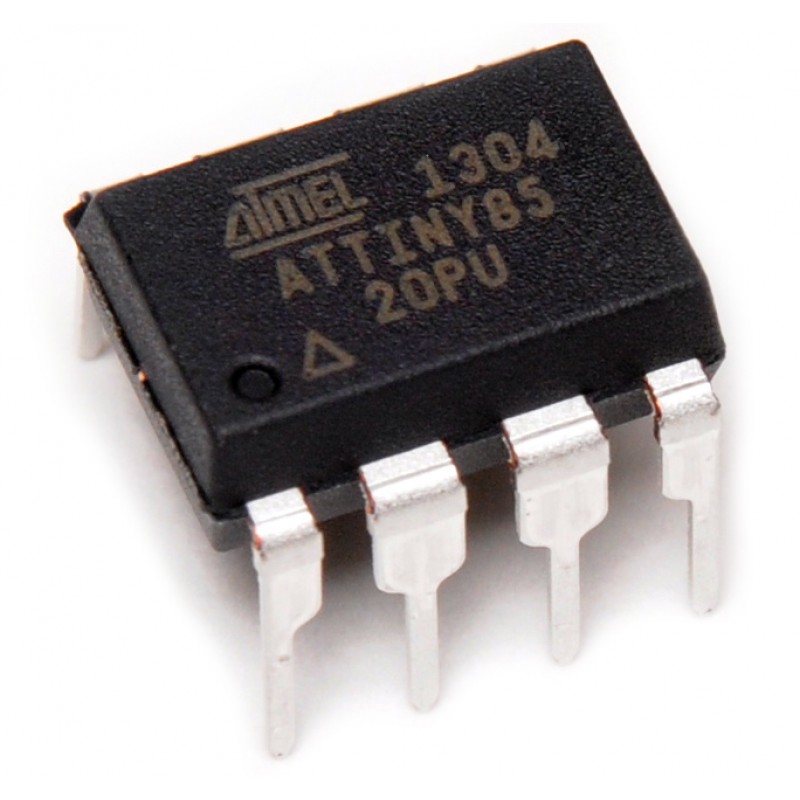
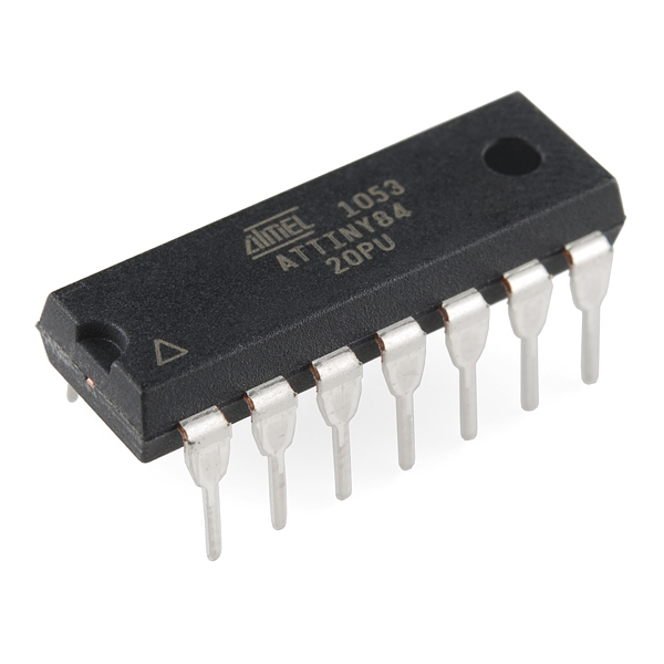
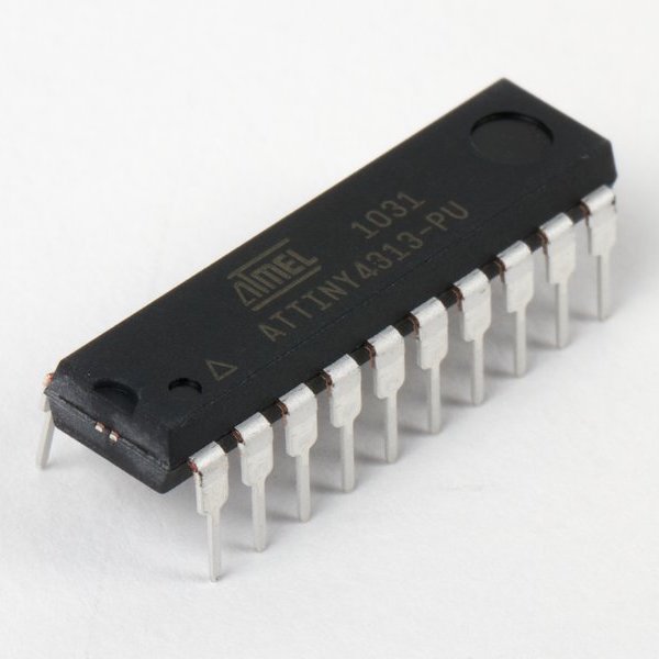
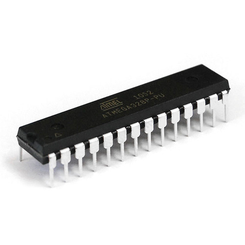
The ATtiny84 is amongst a class of small 8-bit microcontrollers (MCU). ATtinys are like the ATMEGA328P, the heart of the Arduino UNO. They are of the same class, family, and manufacturer – the ATMEL (now Microchip) microcontroller family. We chose the ATtiny84 because the number of GPIO pins available was convenient for the size of the package (and to keep our LED Heart PCB small). Note, that the ATtiny84 can be programmed to control up to 11 pins, however we used 10 in this design. This should not limit you. Feel free to use up to 11 pins, combine two or more LED’s to each pin, and create any design you wish for the PCB Design module or when you prototype the circuit. It does not have to be a heart; some of our past students have made a star, letters, and other creative designs.
A small note on why we have the LED Heart PCB (Printed Circuit Board). This project was originally a Valentine’s Day event workshop by the UCSD IEEE Student Branch. And the heart just stuck after that.
You have the opportunity for flexibility in parts of this project. Keep in mind that the LED Heart project combines creativity with a powerful underlying concept that has far reaching applications and potential by creating your own product that removes the development board from the final product.
| DEVICE | VENDOR URL | QUANTITY | NOTES |
|---|---|---|---|
| Arduino UNO R3 | Digikey | 2 | May use other variants, but may need minor changes to code. |
| USB Cable (A Male to B Male) | Digikey | 2 | |
| ATtiny84 MCU IC 8BIT 8KB FLASH 8DIP | Digikey | 1 | May substitute for any other ATtinyX4 module. |
| CONN IC DIP SOCKET 14POS TIN | Digikey | 1 | |
| BATTERY HOLDER COIN 20MM PC PIN | Digikey | 1 | |
| CR2032 BATTERY LITHIUM 3V COIN 20MM | Digikey | 1 | |
| SWITCH SLIDE SPDT 300MA 4V | Digikey | 1 | |
| RES 10K OHM 1/4W 5% AXIAL | Digikey | 10 | Can substitute for appropriate sized resistor(s). |
| LED BLUE CLEAR T-1 3/4 T/H | Digikey | 10 | Can substitute for any desired color LED. |
| Breadboard (small) | Digikey | 2 | Used for prototyping. |
| Jumper Wire M/M 6 (20pcs) | Digikey | 2 | Used for prototyping. |
| LED Heart PCB | OSH Park | 1 | Latest revision. |
In this module, we will prototype an LED array. This will essentially be the LED Heart, just not in Heart form, and using the Arduino UNO. This is to demonstrate that using the Arduino UNO is a valid method for prototyping. The Arduino UNO is a development board which has the benefits of being easy to use, and the convenient package that the Arduino UNO comes in (i.e. with the labeled header pin arrays). Then we will port over to the appropriate microcontroller for the particular application. In this case, we will be using the ATtiny84. The ATtiny84 is not as convenient as the Arduino UNO; it is simply a microcontroller IC (integrated circuit) package, and not a development board. It does not have the convenient header pins and labels.
Thus, we will construct a simple array of LEDs on a breadboard, and then write a simple program the light up the LEDs using the Arduino UNO. While you work, Keep in mind that we will port this over to an ATtiny84 soon and for the final part - the LED Heart.
We will start off easy with a simple example of toggling an LED ON and OFF.
Construct the following circuit to connect the Arduino UNO to a single LED:
Programming the LED is about as simple as the circuit. The following is the typical blink sketch that is commonly used as the "Hello World" of hardware:
To run the code. Be sure to select:
Then click on the Upload button (or press CTRL/CMD + U) to upload the code to the Arduino UNO.
The behavior should be as follows:
An LED toggling ON and OFF every 500ms (0.5s). Easy right? Now lets build atop this!
In this challenge, we want to prototype our LED Heart using the Arduino UNO. We will have 10 LEDs on our Heart, so we need to expand our single LED example to 10.
Construct a circuit to program 10 LEDs (with the appropriate corresponding resistors) using the Arduino UNO. You may use any valid pins you want.
You may program any behavior you want. We will demonstrate the same behavior as the single LED extended to the array of 10 LEDs. Here is an example of our challenge solution:
Any LED behavior is acceptable, as long as all the LEDs demonstrate functionality.
Keep in mind, you will have the opportunity to program a beautiful lightshow later!
If you are using the Arduino IDE's Serial Monitor, then the LED on pin 0 and 1 may behave wonky when writing to it. Pin 0 (RX) and pin 1 (TX) are shared with the Serial Monitor (e.g. when you use Serial.print(...)) so any device (e.g. LED) may receive a HIGH or LOW signal even if you are explicitly writing a particular value to it (or not).
Note that this solution is NOT the only solution. This is just how we realized it. It should look almost exactly the same as the code we started with when testing the single LED. The only difference is the addition of several more LEDs. We also employed an array for its ease, convenience, and code readibilty.
The schematic should be similar to the following:
Again, the code can vary, but here is what we have for our solution:
Hopefully this challenge was not too difficult, this was meant to be very simple - after all, we just started. The value in this project is to demonstrate the transition from prototyping to product!
In this module, we introduce AVR microcontrollers made by Microchip Technology, formerly ATMEL. We will focus on one family of AVR microcontrollers: tinyAVR. From the tinyAVR family we will use the ATtiny84. Each microcontroller is different in its own ways with various features.
This module aims to familiarize you with the ATtiny84 to replace the Arduino UNO that we have been using to prototype.
To learn about AVR microcontrollers in general we direct you to our AVR Microcontrollers tutorial. You will need to follow the sections for ATtinys since we will be using an ATtiny variant in this project. We will be using the Arduino UNO as an ISP as our bootloading device, you may skip any mentions of the Sparkfun Pocket AVR Programmer.
After reviewing the AVR microcontrollers tutorial, you should have the ATtinyCore bootloaders installed, and be familiar with the board settings for ATtinys.
Next, we will introduce the ATtiny84 and how we will be using it in this project!
We will now cover the ATtiny84 in detail as it pertains to the LED Heart. That is, how we will use the ATtiny84 to replace the Arduino UNO to light up the LEDs that make up the heart.
The benefits of the ATtiny84 as the microcontroller for our LED Heart is that it is extremely small and has just the right number of pins to be a perfect fit for the number of LEDs on our Heart. We used the Arduino UNO to do our prototyping, and now we need to port our pin mapping and code to the ATtiny84.
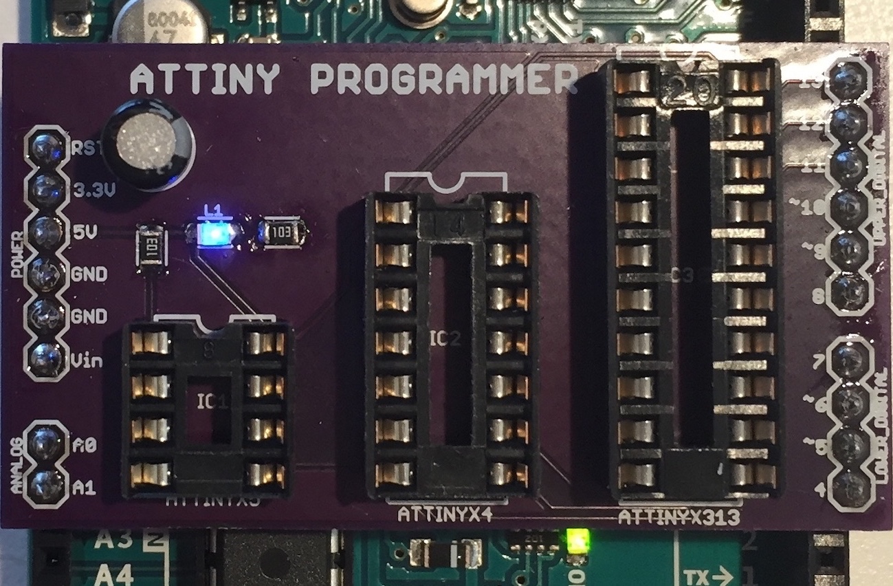
Now we will cover the ATtinyX4 series in general and then how we will use the ATtiny84 explicitly in the LED Heart. To learn about the ATTinyX4, we direct you to our ATtinyX4 Microcontroller tutorial. Since we will be using the Arduino UNO as an ISP, you only need to pay attention to the sections pertaining to the Arduino as ISP explicitly to bootload and program the ATtiny84. We cover the ATtinyX4 through-hole package in the general tutorial; it is also the same package we use in the LED Heart.
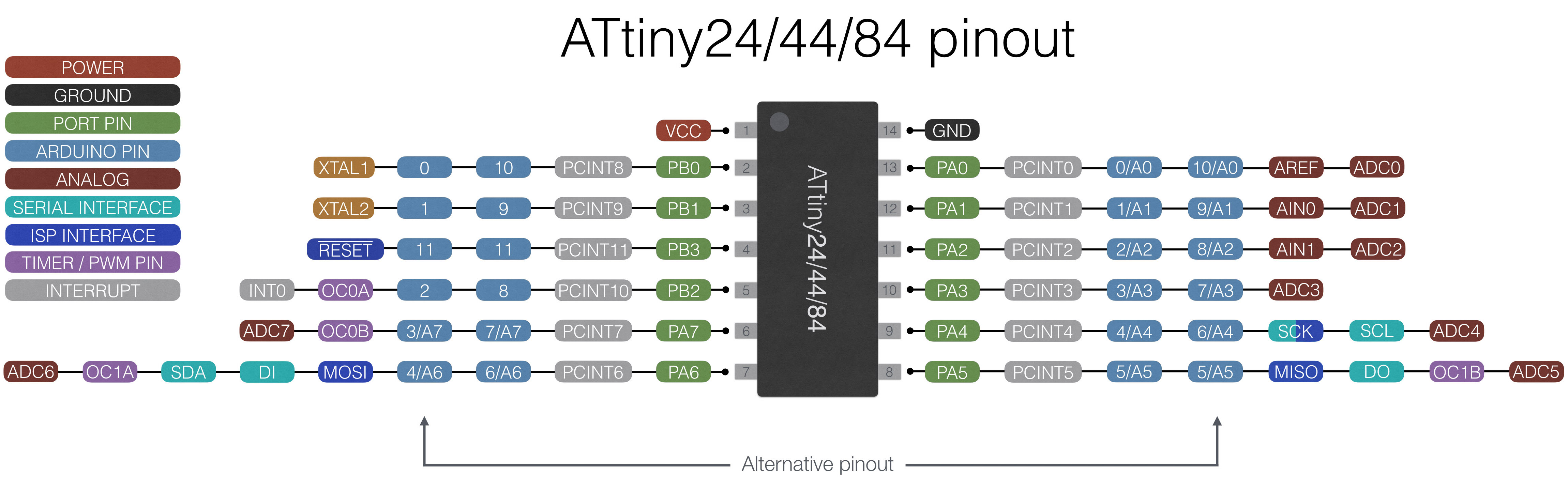
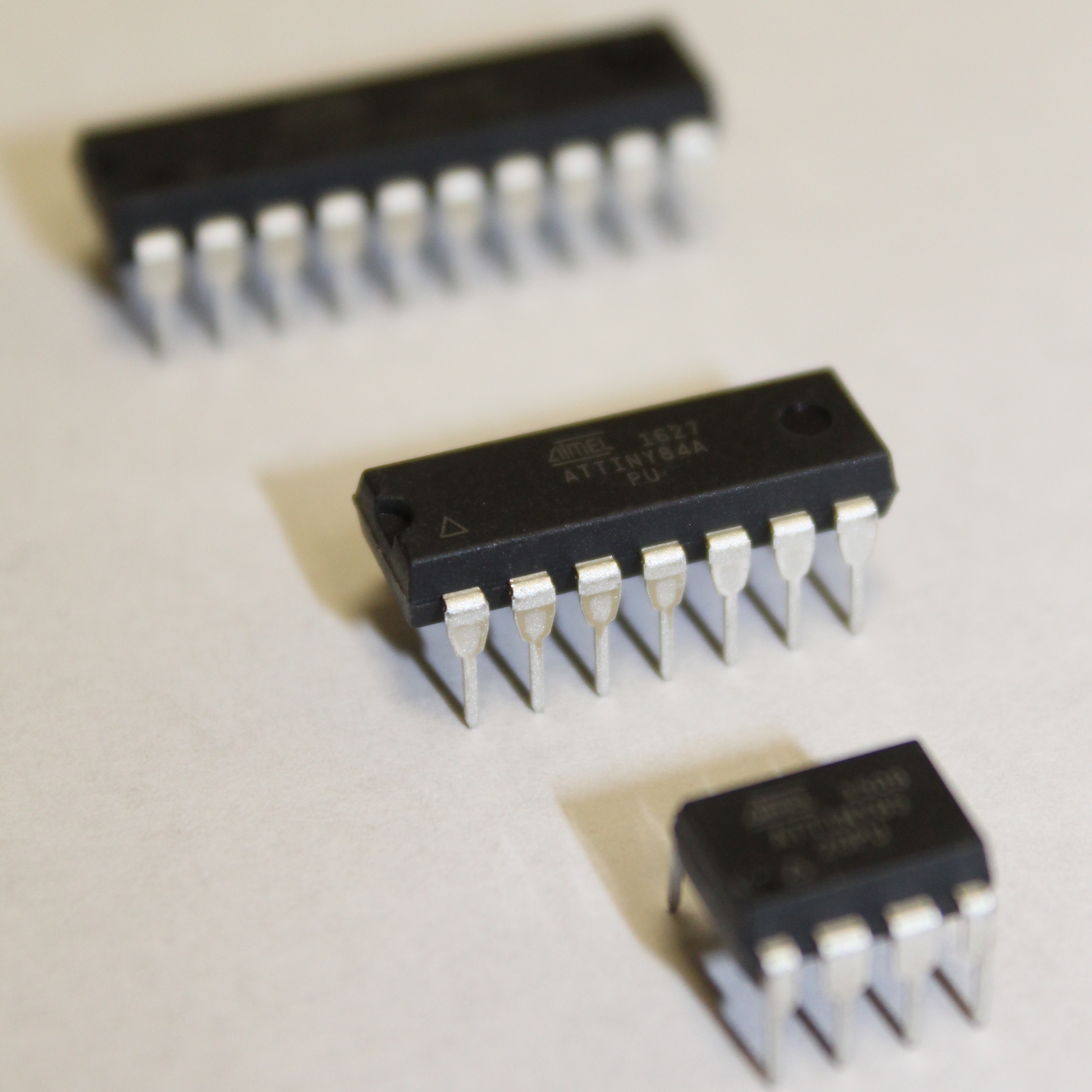
Here we show a reference of the ATtiny84 pinout:
This pinout describes the physical and logical layout of the ATtiny84. The physical layout are the physical pins - pins one through eight in a counter-clockwise fashion. The logical layout of the ATtiny84 are the numerous labels tied to each physical pin.
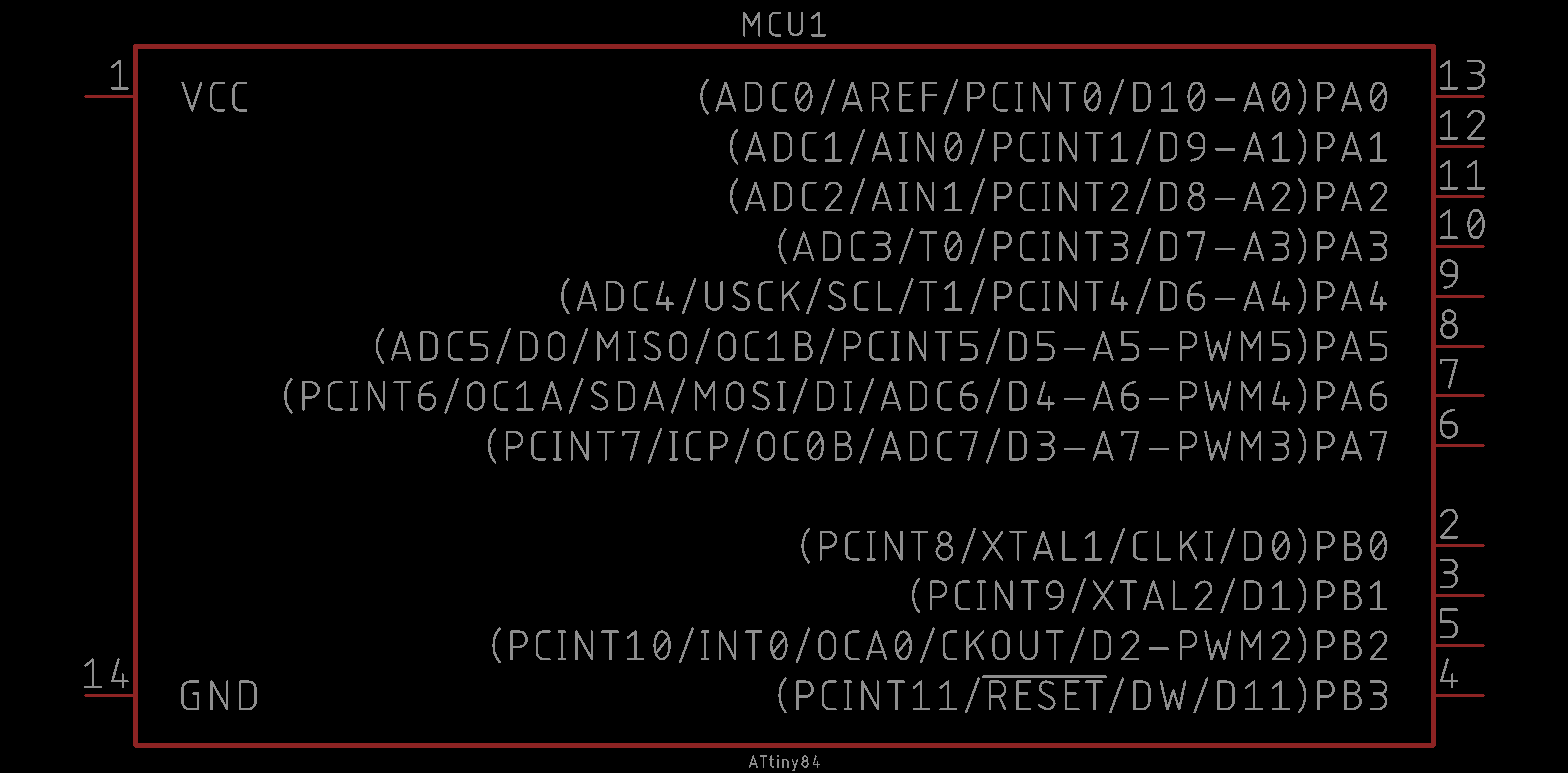
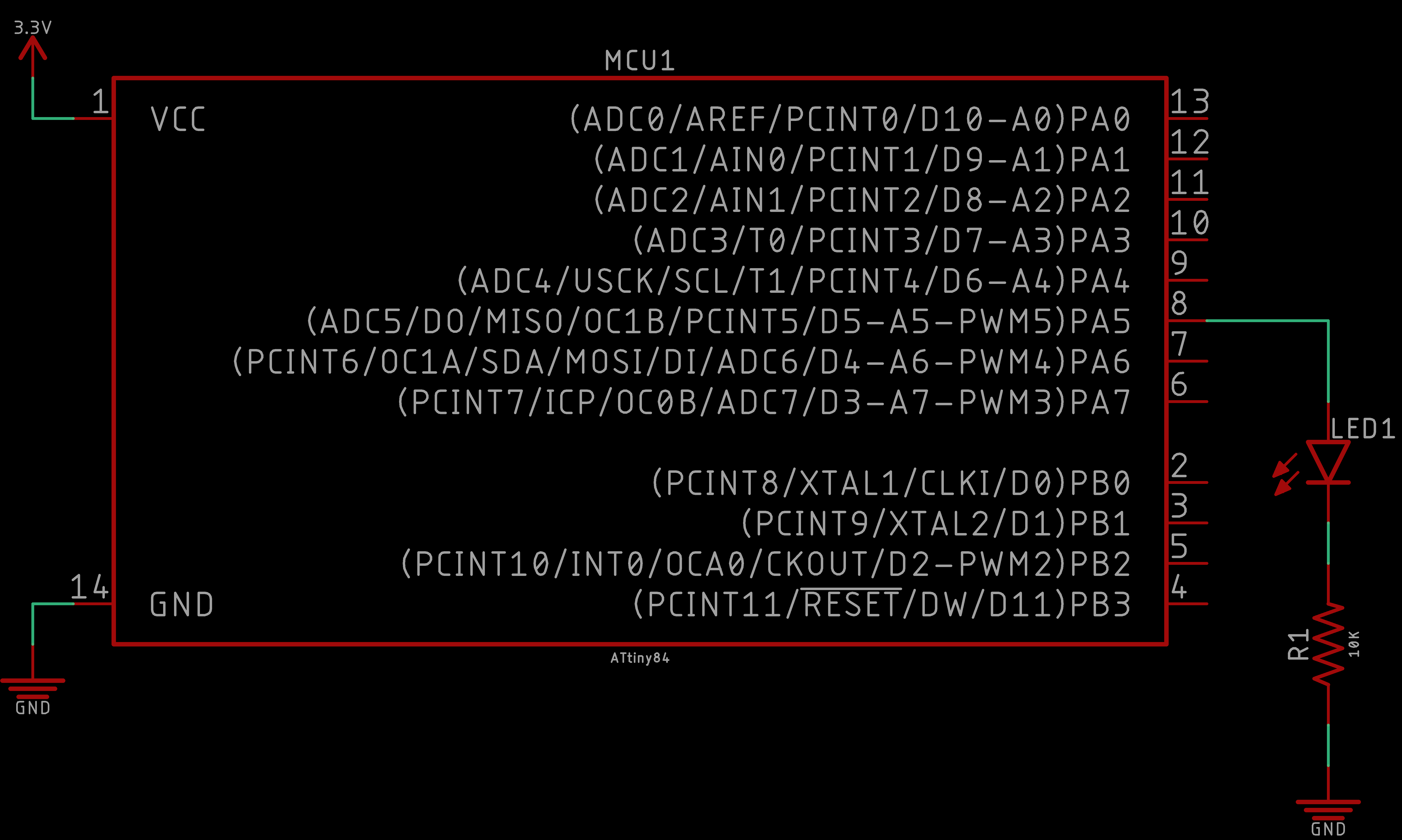
We have the ATtiny84 device in our EAGLE libraries and it is represented as follows:
Observe the similarities and differences. The numbers represent the physical layout of the ATtiny84. However, the order of these numbers do not match the physical layout of the ATtiny84. The reason is because they are organized logically. On the left, the power connections are shown (i.e. VCC and GND). On the right, the GPIO (general purpose input and output) pins are labeled and ordered by port (e.g. PB = port B).
Each of the GPIO pins have one or more functions. The pins that you can program using the ATtinyCore in the Arduino IDE are labeled on the far right inside the parentheses (e.g. D# for a digital input or output pin, A# for an analog input pin, PWM# for a digital PWM or analog output pin). You would use these pins like you would in any typical Arduino sketch.
In this challenge, we will explicitly program the ATtiny84. Follow the ATtinyX4 Microcontroller tutorial closely and program the ATtiny84 to simply blink an LED. We will be using the Arduino UNO as an ISP as our bootloading device, you may skip any mentions of the Sparkfun Pocket AVR Programmer.
Here is the behavior of the challenge simplying blinking an LED:
Note that this solution is NOT the only solution. This is just how we realized it.
The schematic should be similar to the following:
As for the code, we took the Blink example from the Arduino UNO library of examples and modified the pin number to one appropriate on the Attiny84:
Again, the results are as follows:
And that is it! Your ATtiny84 should be blinking an LED. This was a trivial example, but it is the first stepping stone to making more interesting functionality.
In the last challenge, we prototyped our LED Heart using the Arduino UNO; now we will prototype our LED Heart using the ATtiny84.
If you have not yet, bootload your ATtiny84 using the Arduino UNO as an ISP. We recommend choosing the Counterclockwise (like the old ATtinyCore and x41-series) for your Pin Mapping since the PCB (to come) has been designed using this Pin Mapping.
Construct a circuit to program 10 LEDs (with the appropriate corresponding resistors) using the ATtiny84. We recommend using the following pins (to match the PCB to come): 10, 9, 8, 7, 6, 5, 4, 3, 2, 1.
To power the ATtiny84, you may use the 3V CR2032 coin cell battery in the battery retainer or you can use the 3.3V pin on the Arduino UNO power rail. Although inconvenient, we recommend using the 3V battery because the LED brightness will be appropriately approximated. Thus, if you want to adjust the resistor values to obtain a desired LED brightness, you can do so at this stage.
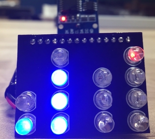
You may program any behavior you want. We will demonstrate the same behavior as the single LED extended to the array of 10 LEDs. Here is an example of our challenge solution:
Any LED behavior is acceptable, as long as all the LEDs demonstrate functionality.
Keep in mind, you will have the opportunity to program a beautiful lightshow soon!
Note that this solution is NOT the only solution. This is just how we realized it. It should look almost exactly the same as the code we started with when testing the single LED. The only difference is the addition of several more LEDs. We also employed an array for its ease, convenience, and code readibilty.
The schematic should be similar to the following:
Again, the code can vary, but here is what we have for our solution:
Hopefully this challenge was not too difficult, this was meant to be very simple - after all, we just started. The value in this project is to demonstrate the transition from prototyping to product!
We now turn to PCB design to advance our breadboard prototype into a PCB (printed circuit board) product. We will design the PCB the LED Heart using the Autodesk EAGLE software.
In this module, we will take you through the process to transform our lame breadboard design into a full fledged product in the shape of a heart!
So we ask that you pay very close attention to the way we are designing the PCBs here so that you can take what you observe and learn here into practice for your own future projects! Feel free at any point to deviate and add your own spin on the design.
Although we will be designing a Heart and welcome you to do the same. We also encourage you to design your own shape instead, or your own after! You will learn a lot more through your own design.
If you have never used EAGLE or need a refresher, we have an Introduction to EAGLE PCB Design tutorial that we encourage you to follow. This tutorial will also get you started downloading and installing EAGLE. Furthermore, this will get you equipped with the basics so that you can keep up with the pace of the EAGLE content in this project. In these modules, we proceed slowly, however we are not going to go over the basic tools of EAGLE and assume you have the EAGLE Libraries integrated into the EAGLE environment.
First, we create the ATtiny schematic. This is pretty straight forward as we have already prototyped the ATtiny84 with 10 LEDs. The addition here is that of the 3V CR2032 coin cell battery and a small SMD switch.
Before going onto the board, we need to obtain our Heart (or any other shape) DXF. Browse the web for some simple shapes with high contrast. Next follow module 02 of our Introduction to Inkscape tutorial. By the end of the tutorial you should have your DXF. The instructions in the Inkscape tutorial explain importing it into EAGLE, and we also do it in the next video.
Next, we import the Inkscape DXF of our board dimensions into EAGLE. Then we place all our components to prepare for routing.
We complete the PCB board design by routing the entire board and placing our product labels.
Finally, we debug our LED Heart and see what our resulting product looks like in Fusion360 and an OSH Park board render.
With the PCB design complete we are now ready to solder a replica of the LED Heart PCB!
In this module we will solder a replica of the PCB boards we just designed. We will be soldering a single SMD component followed by several through-hole components. We will use a standard soldering iron pen to solder the LED Heart.
Please take your time in this module as soldering is a relaxing and peaceful art. You should only solder when you are relaxed and stress free. Why? Because when you solder there should only be three things present: You, the board, and zen.
The point is, do not rush this and do it right the first time. We always say, the right way to solder is to do it right the first time. It is easy to make mistakes when soldering, but it is much harder to fix any soldering mistakes. Well... as you develop experience, fixing mistakes gets easier, but it very frustrating when you are not comfortable with the process.
In this first video we remove the artifacts from OSH Park's panelization of our board during the manufacturing process. After we place the 10 resistors into the PCB.
We proceed to solder the resistors into the LED Heart PCB, the switch on the backside of the PCB, and 14-pin DIP socket for the ATtiny84
Next, we solder 8 of the 10 LEDs (skipping the top and bottom LEDs).
Note the polarity of your LEDs!
Finally we wrap up the LED Heart soldering the 20mm coin cell battery retainer, followed by the last two LEDs.
We have completed the soldering of the LED Heart! Now it is ready to program with your light show!
In this module, we add the finishing touches to complete the LED Heart.
The assembly of the heart is straight forward, and you probably have already assembled it. Simply place the CR2032 battery into the coin cell retainer. There is a polarity to it. The anode (positive) side of the battery will be facing right-side up.
Then place the ATtiny84 with pin 1 right-side up (e.g. the dip or cresent-moon marking is oriented upwards) into the DIP connector.
Be gentle when inserting the ATtiny into the DIP connector!
Always use an IC remover when removing the ATtiny!
If your ATtiny84 is still programmed and you used the LED pins we recommended. Then, when you flip the switch of the LED Heart, all ten LEDs should behave as they did in module 02 AVR Microcontrollers: ATtiny84.
If it does not, try to program the ATtiny84 again. If it still fails to work, check the orientation of the ATtiny84 on the LED Heart PCB. Check for shorts, continuity, and voltage across the appropriate points on the PCB.
Now that we have our working LED Heart. It is time to program our LED Heart lightshow!
In this challenge, we finally program the LED Heart lightshow.
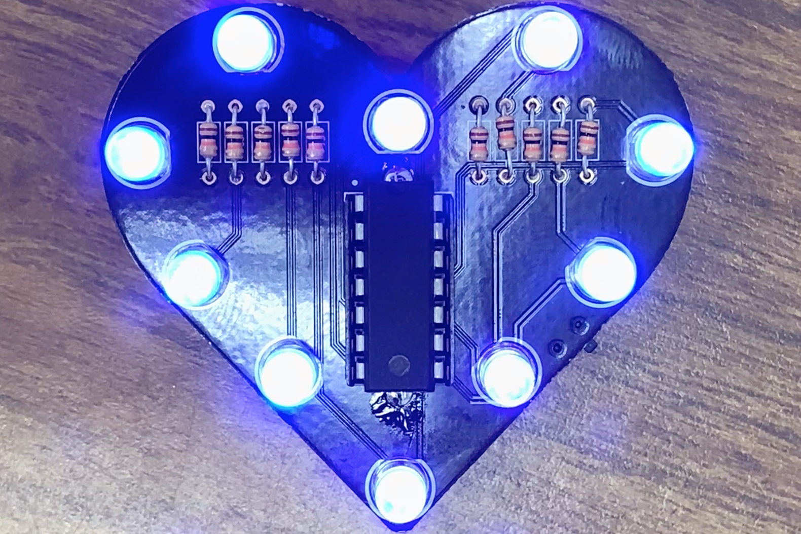
You may program any behavior you want. Here is an example of our LED Heart lightshow:
Our LED Heart lightshow is not the most amazing. We encourage you to be creative and make an awesome lightshow!
This concludes the LED Heart! We see the Aruino UNO (or other variant) in a new light and as it is meant to be - a development board. Then we explored options to program an ATtiny microcontroller to perform the same role as the Arduino UNO thus reducing cost, reducing area, and increasing overall efficiency.
We took our prototype to product making a custom PCB in a unique shape. We used Inkscape to take any generic and simple image from the web and created a DXF to import into EAGLE.
Then programmed a radiant lightshow to show off our soldered LED Heart!
We hope this project inspires you to explore ATtiny microcontrollers in your future projects and to make fun and creative projects!