Create your own remote controlled car from scratch!
Designed by:
Colin "MrSwirlyEyes" Keef
and
Buu Truong
The bluetooth remote control car (BT RC Car) is a wirelessly controlled remote control vehicle. Unlike most remote control (RC) cars you can buy from a hobby store, this RC car can be built from scratch - that is, both the vehicle AND the remote! It is quite zippy, and the handling is decent. However, it is limited in terms of terrain - not recommended for slopes or outside in general. But it is great to keep at your desk or office, to entertain your cats (:3), and for educational purposes. We teach a ton of concepts that go into creating our BT RC Car! How to communicate from device-to-device (e.g. Arduino to Arduino) using a bluetooth module, how to CAD - both PCB and 3D model - your car, programming AVR microcontrollers, and general prototyping circuitry.
| DEVICE | VENDOR URL | QUANTITY | NOTES |
|---|---|---|---|
| Arduino UNO R3 | Digikey | 2 | May use other variants, but may need minor changes to code. |
| USB Cable (A Male to B Male) | Digikey | 2 | |
| [Optional] POCKET AVR PROGRAMMER | Digikey | 1 | Used to bootload AVR microcontrollers. |
| SERIAL PROGRAMMER IC BRIDGE USB-UART 3.3V MODULE | Digikey | 1 | Used to program ATMEGA328p (BT RC Car vehicle). |
| [Optional] USB Cable (A Male to Mini B Male) | Digikey | 1 | Used for both Pocket AVR Programmer and Serial Programmer. |
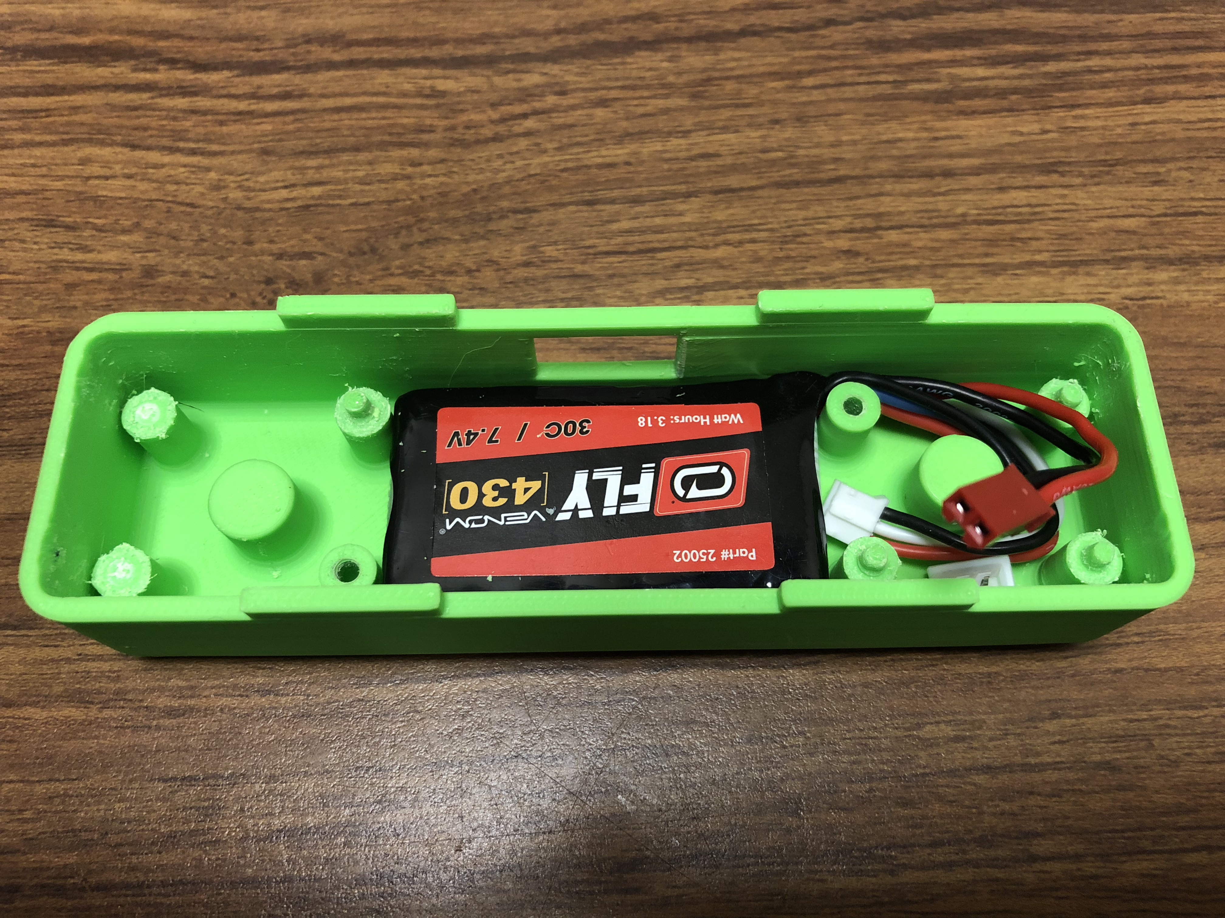
| Venom Fly 30C 2S 430mAh 7.4V LiPo Battery | Venom Power | 2 | Any 7.4 (2S) substitute is fine. One for remote PCB. One for vehicle PCB. |
| 10 Pairs 100mm JST 2 Pin Connector Plug Lead Wire Male & Female Wire 22AWG | Amazon | 1 | Need two female connectors. One for remote PCB. One for vehicle PCB. |
| DRV8838 Single Brushed DC Motor Driver Carrier | Pololu | 1 | Used for prototyping. |
| Jumper Wire M/M 6 (20pcs) | Digikey | 2 | Used for prototyping. |
| Breadboard (small) | Digikey | 2 | Used for prototyping. |
| DEVICE | VENDOR URL | QUANTITY | NOTES |
|---|---|---|---|
| CAP CER 0.1UF 50V 0805 | Digikey | 6 | |
| RES SMD 10K OHM 1% 1/8W 0805 | Digikey | 2 | |
| RES SMD 1K OHM 5% 1/8W 0805 | Digikey | 2 | |
| CAP CER 1UF 25V 0805 | Digikey | 2 | |
| SWITCH SLIDE SPDT 300MA 4V | Digikey | 1 | |
| ATTINY85V IC MCU 8BIT 8KB FLASH 8SOIC | Digikey | 1 | |
| LED BLUE CLEAR SMD 0805 | Digikey | 1 | |
| LED GREEN CLEAR SMD 0805 | Digikey | 1 | |
| Bluetooth 4.0 HM-10 BLE Module | Amazon | 2 | |
| (1x06) CONN FEMALE 6POS .100" R/A TIN | Digikey | 1 | |
| VOLTAGE REG IC LINEAR 3.3V 300MA SOT23-5 | Digikey | 1 | |
| (2x03) CONN HEADER 6POS .100" STR 15AU | Digikey | 1 | |
| 10pcs Joystick Breakout Module | Amazon | 1 | Only need 2 for the remote. |
| (1x05) CONN FEMALE 5POS .100" R/A TIN | Digikey | 2 | |
| BT RC Car Remote PCB | 1 | Rev 6 |
| DEVICE | VENDOR URL | QUANTITY | NOTES |
|---|---|---|---|
| CAP CER 0.1UF 50V 0805 | Digikey | 6 | |
| CAP CER 100UF 10V 1210 | Digikey | 2 | |
| RES SMD 10K OHM 1% 1/8W 0805 | Digikey | 2 | |
| CAP TANT POLY 10UF 16V 1206 | Digikey | 1 | |
| CAP CER 10UF 35V 0805 | Digikey | 2 | |
| CRYSTAL 16.0MHZ 18PF SMD | Digikey | 1 | |
| CAP CER 12PF 250V 0805 | Digikey | 2 | |
| CAP CER 1UF 25V 0805 | Digikey | 2 | |
| Switch Toggle SPDT 5A 120V | Digikey | 1 | |
| Brushed DC Motor: 130-Size, 6V, 11.5kRPM, 800mA Stall | Pololu | 1 | |
| ATMEGA328p IC MCU 8BIT 32KB FLASH 32TQFP | Digikey | 1 | |
| VOLTAGE REG IC LINEAR 6V 1A 8HTSOP-J | Digikey | 1 | |
| LED BLUE CLEAR SMD 0805 | Digikey | 1 | |
| RES SMD 1K OHM 5% 1/8W 0805 | Digikey | 2 | |
| IC DRV8838D H-BRIDGE DRIVER PAR 8WSON | Digikey | 1 | |
| (1x06) CONN HEADER .100" SINGL STR 6POS | Digikey | 2 | |
| Bluetooth 4.0 HM-10 BLE Module | Amazon | 2 | |
| (1x06) CONN HEADER FEMALE 6POS .100" TIN | Digikey | 1 | |
| VOLTAGE REG IC LINEAR 5V 300MA SOT23-5 | Digikey | 1 | |
| 4 x MG90S Metal Geared Micro Servo | Amazon | 1 | Only need 1 for the vehicle. Good to have spares though! |
| (2x03) CONN HEADER 6POS .100" STR 15AU | Digikey | 1 | |
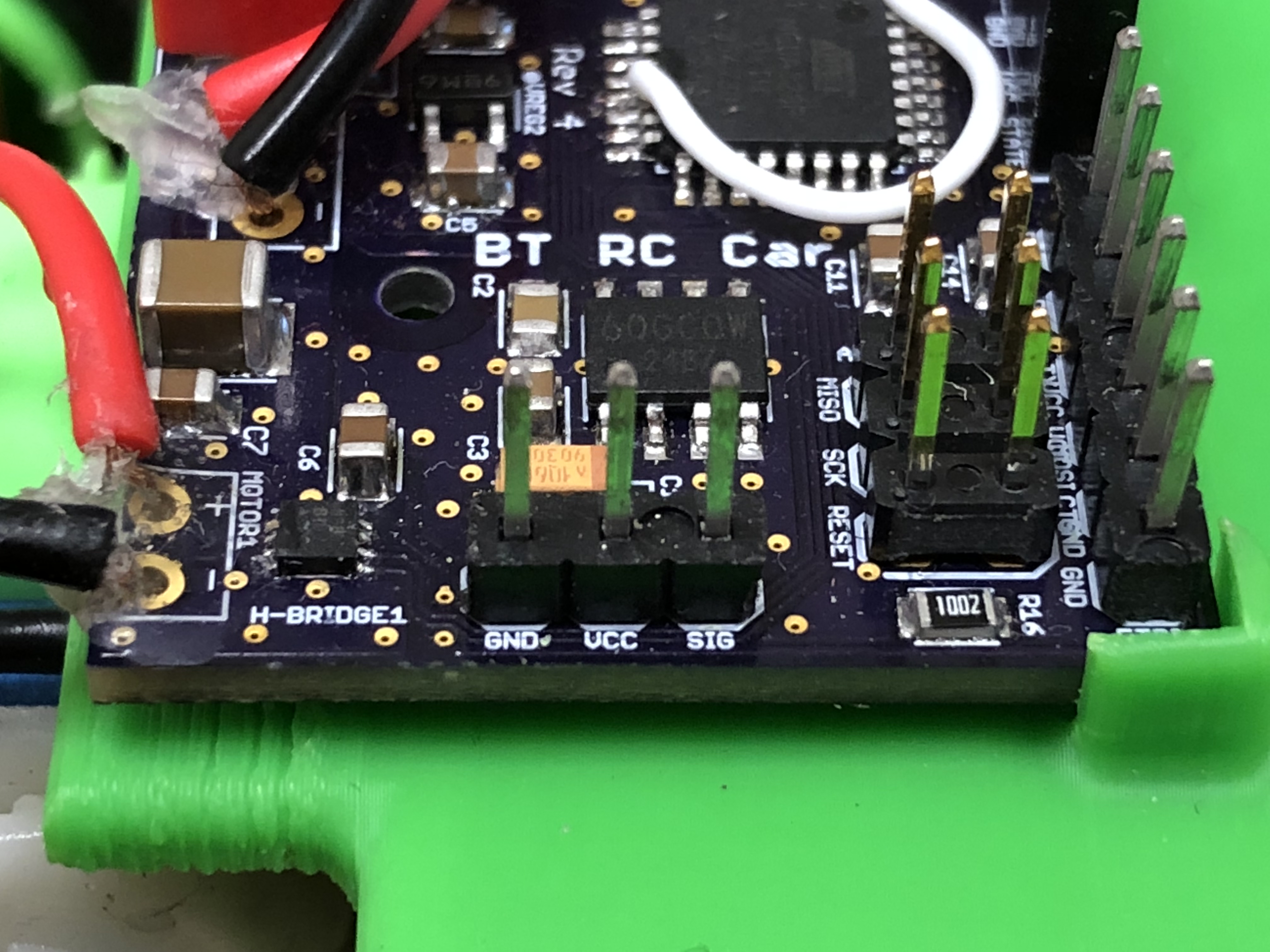
| BT RC Car Vehicle PCB | 1 | Rev 6 |
| DEVICE | VENDOR URL | QUANTITY | NOTES |
|---|---|---|---|
| Black-Oxide Alloy Steel Socket Head Screw M3 x 0.5 mm Thread, 16 mm Long | McMaster-Carr | 2 | |
| High-Strength Steel Hex Nut Class 10, M3 x 0.5 mm Thread | McMaster-Carr | 6 | |
| Black-Oxide Alloy Steel Socket Head Screw M3 x 0.5 mm Thread, 60 mm Long | McMaster-Carr | 1 | |
| Black-Oxide Alloy Steel Socket Head Screw M3 x 0.5 mm Thread, 8 mm Long | McMaster-Carr | 5 | |
| Black-Oxide Alloy Steel Socket Head Screw M2 x 0.4 mm Thread, 20 mm Long | McMaster-Carr | 2 | |
| 316 Stainless Steel Washer for M3 Screw Size, 3.2 mm ID, 7 mm OD | McMaster-Carr | 2 | |
| 316 Stainless Steel Washer for M2 Screw Size, 2.2 mm ID, 5 mm OD | McMaster-Carr | 4 | |
| Zinc-Plated Steel Hex Nut Medium-Strength, Class 8, M2 x 0.4 mm Thread | McMaster-Carr | 2 | |
| 693ZZ Miniature Shielded Bearing 3mm x 8mm x 4mm | Amazon | 4 | |
| LM Wide High Grip Tire (30/4pc) | Kyosho | 1 |
In this module, we will lightly go over each part of the BT RC Car from a high-level perspective. That is, how each entity is connected to each other. Essentially, we are setting up for what is to come so that when you are working on the smaller details, you will know how they are connected in the bigger picture. The remaining modules will go into these same components at a lower-level and in great detail. There will also be modules with integration that use components from the previous modules.
Without further adieu, let us make fun!
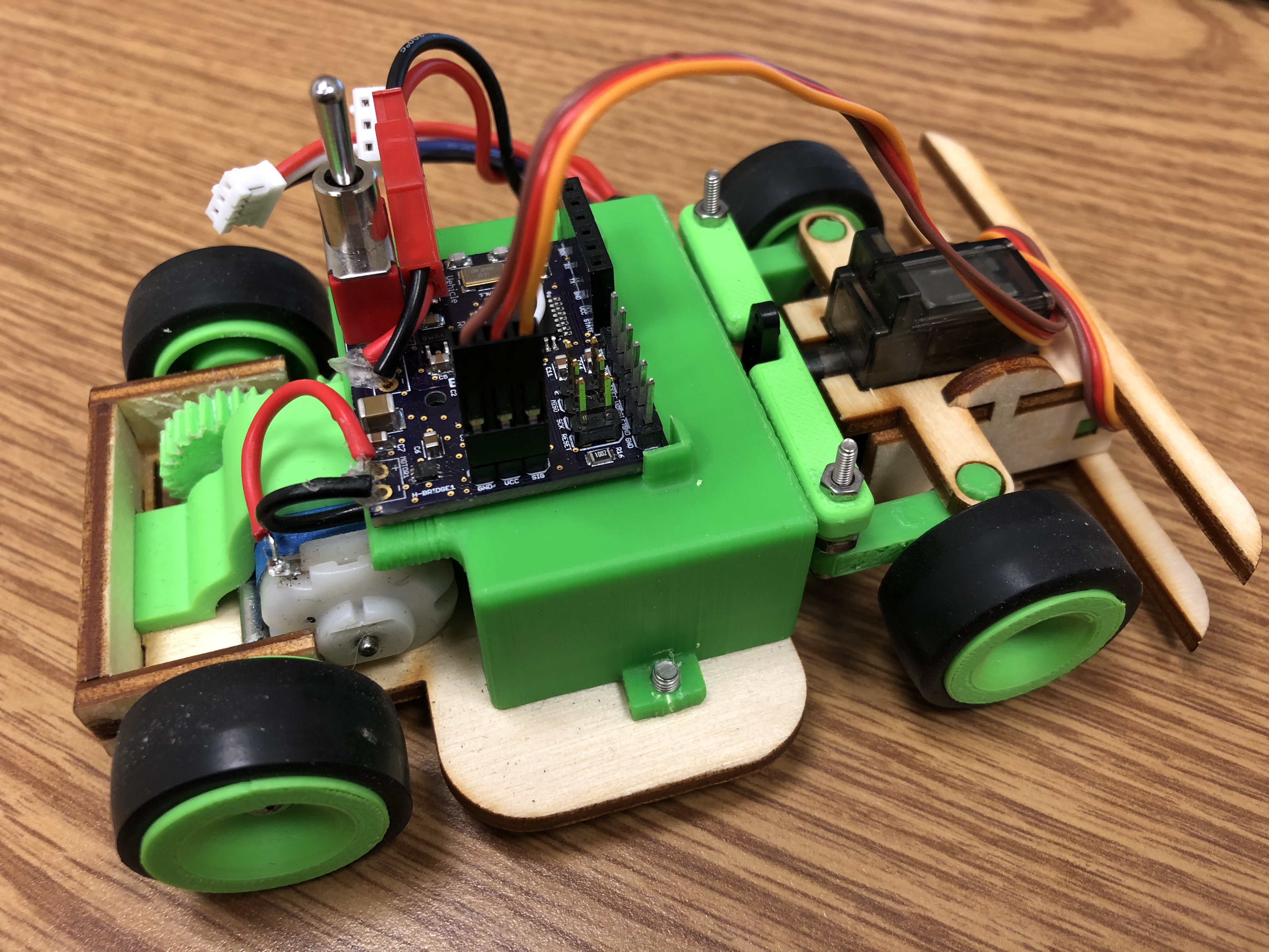
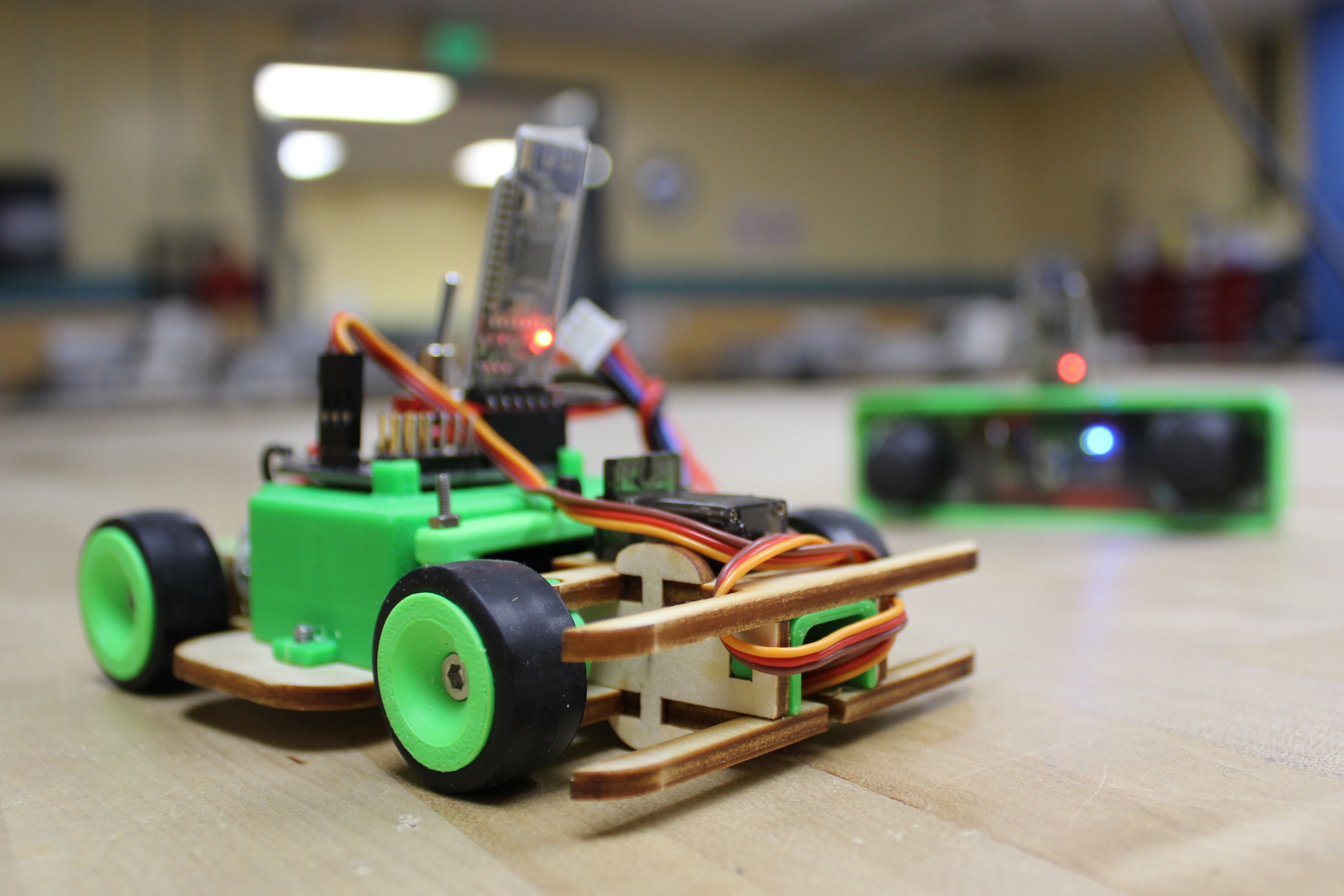
The end-product of this project is twofold:
Naturally, both of these devices work in tandem. The remote transmits data to the vehicle. We make a point here now to point out that we are designing this project for one-way communication only. That is, the remote will transmit data to the vehicle, and not vice-versa. It is certainly possible for this projec to utilize two-way communication with the appropriate changes in code, however we do not employ such by design.
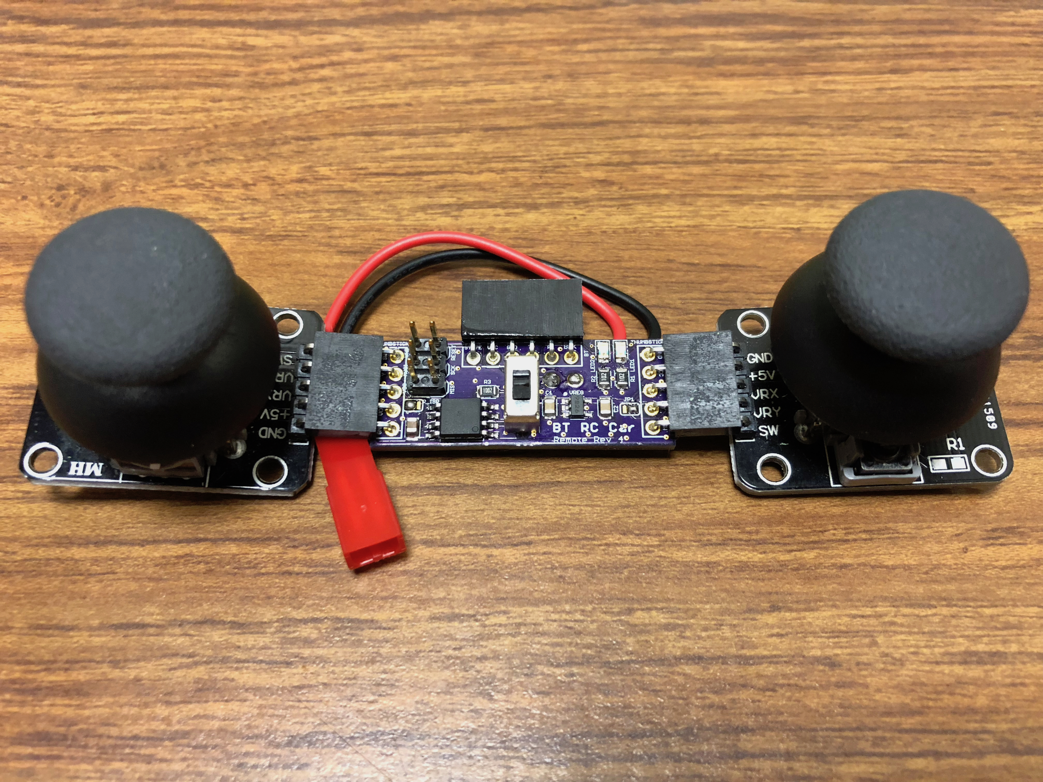
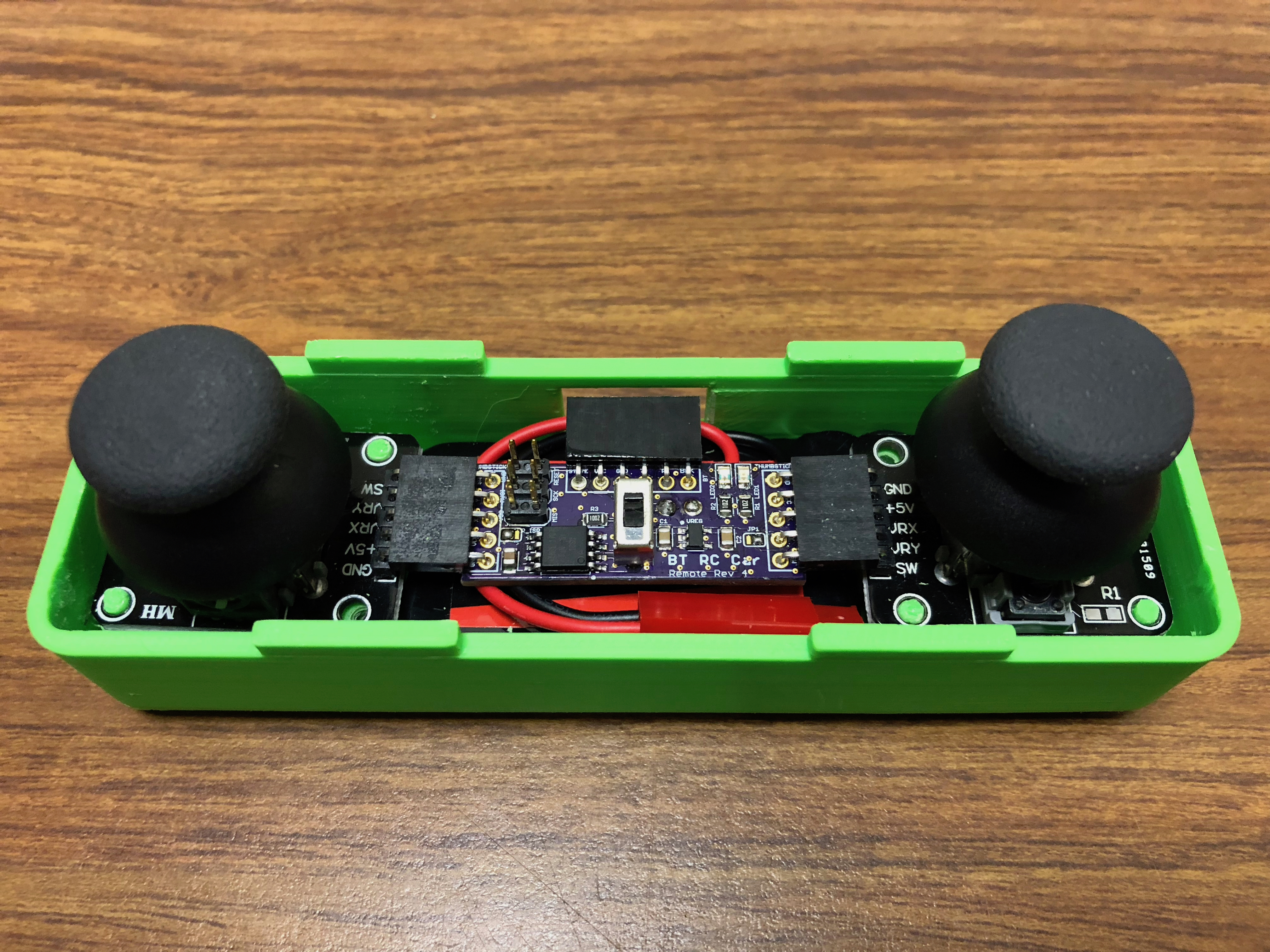
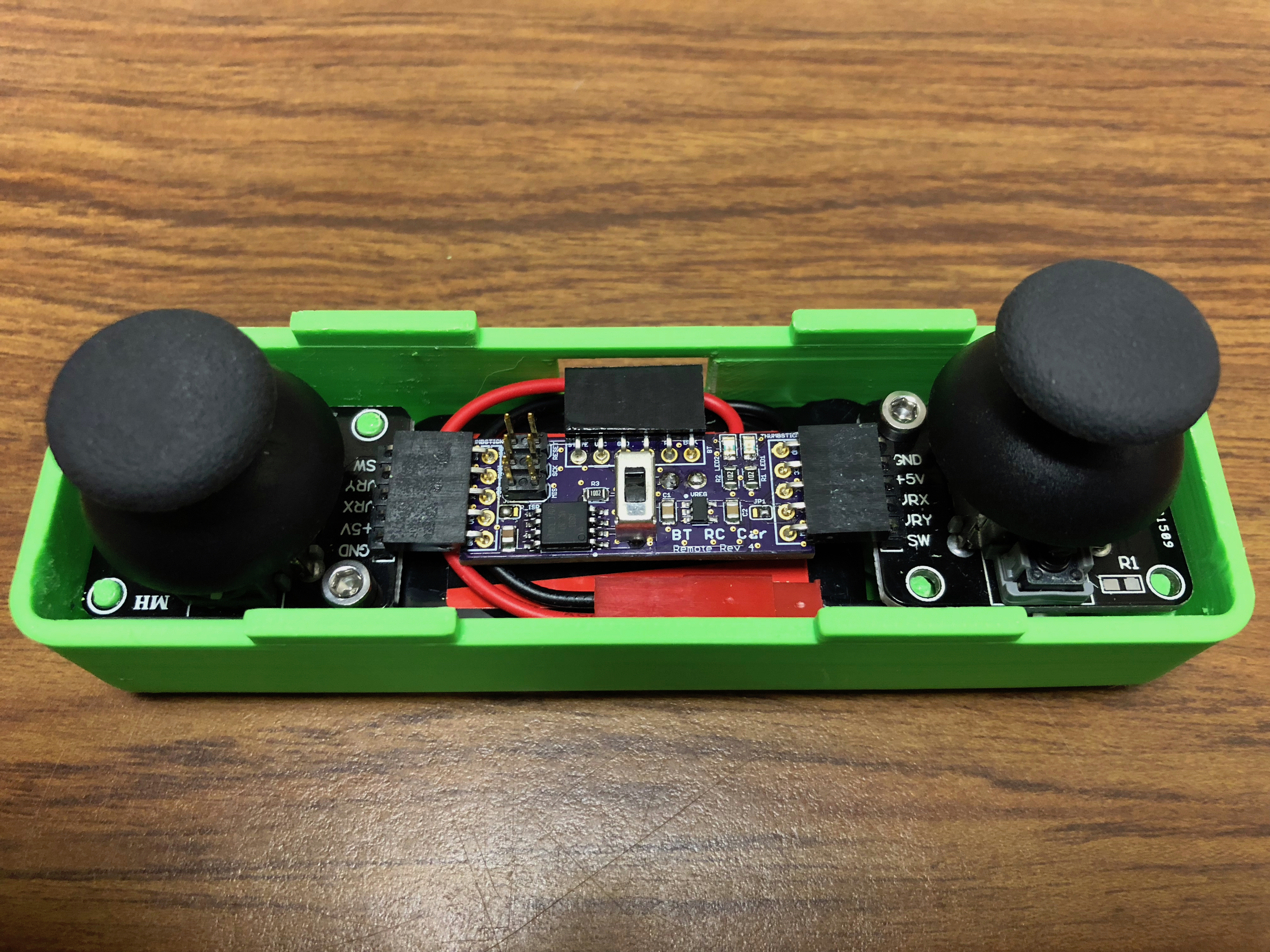
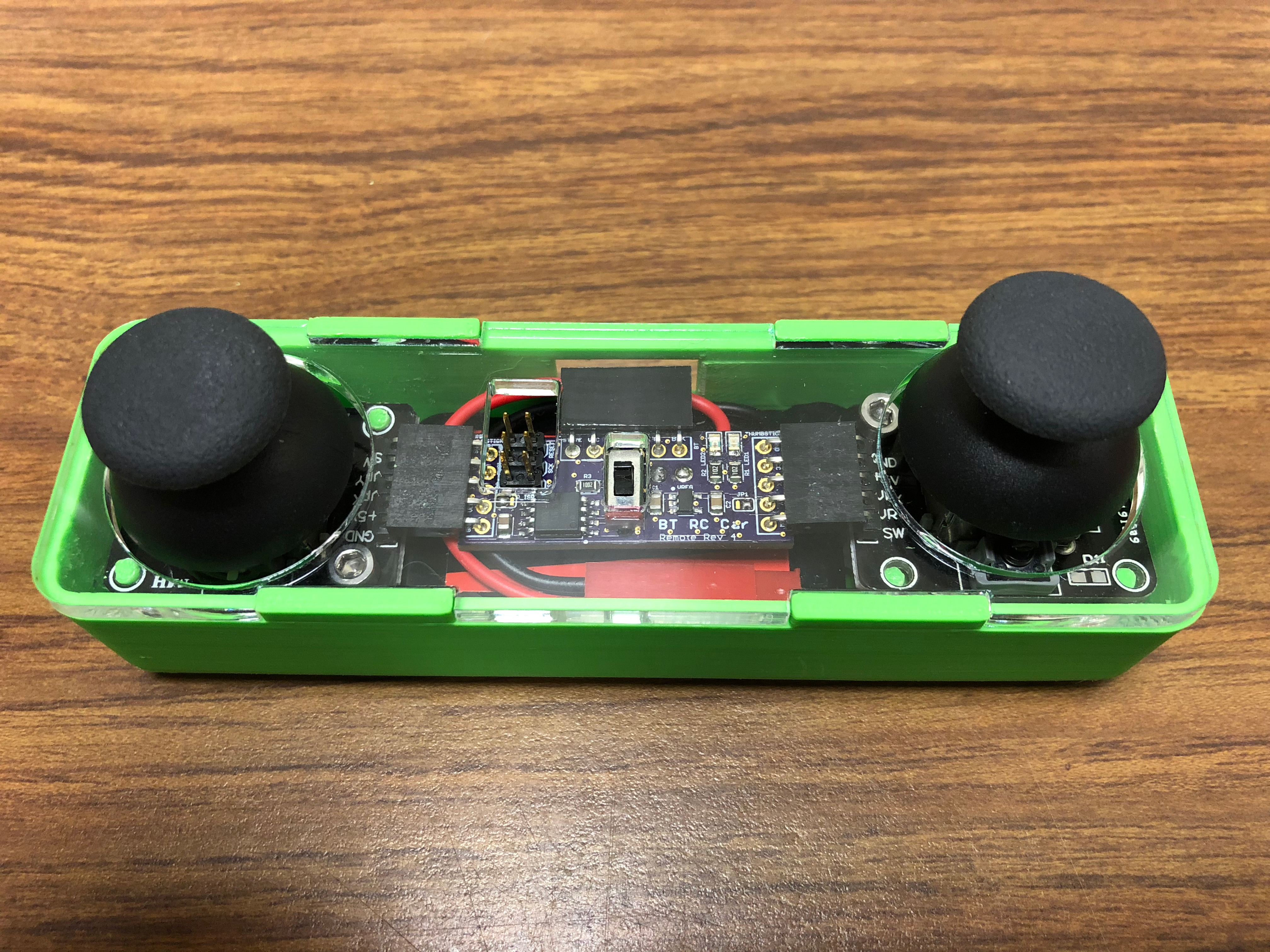
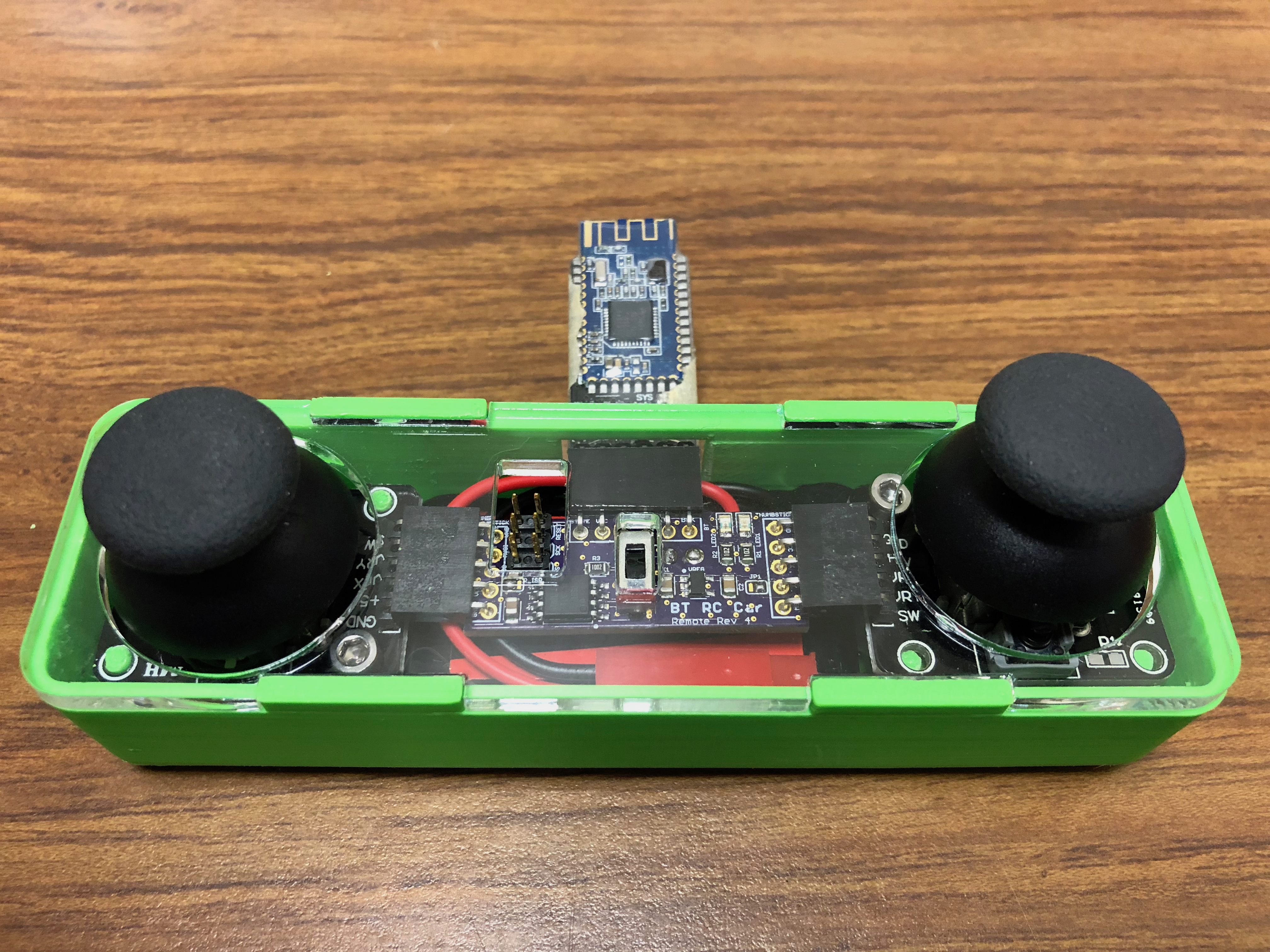
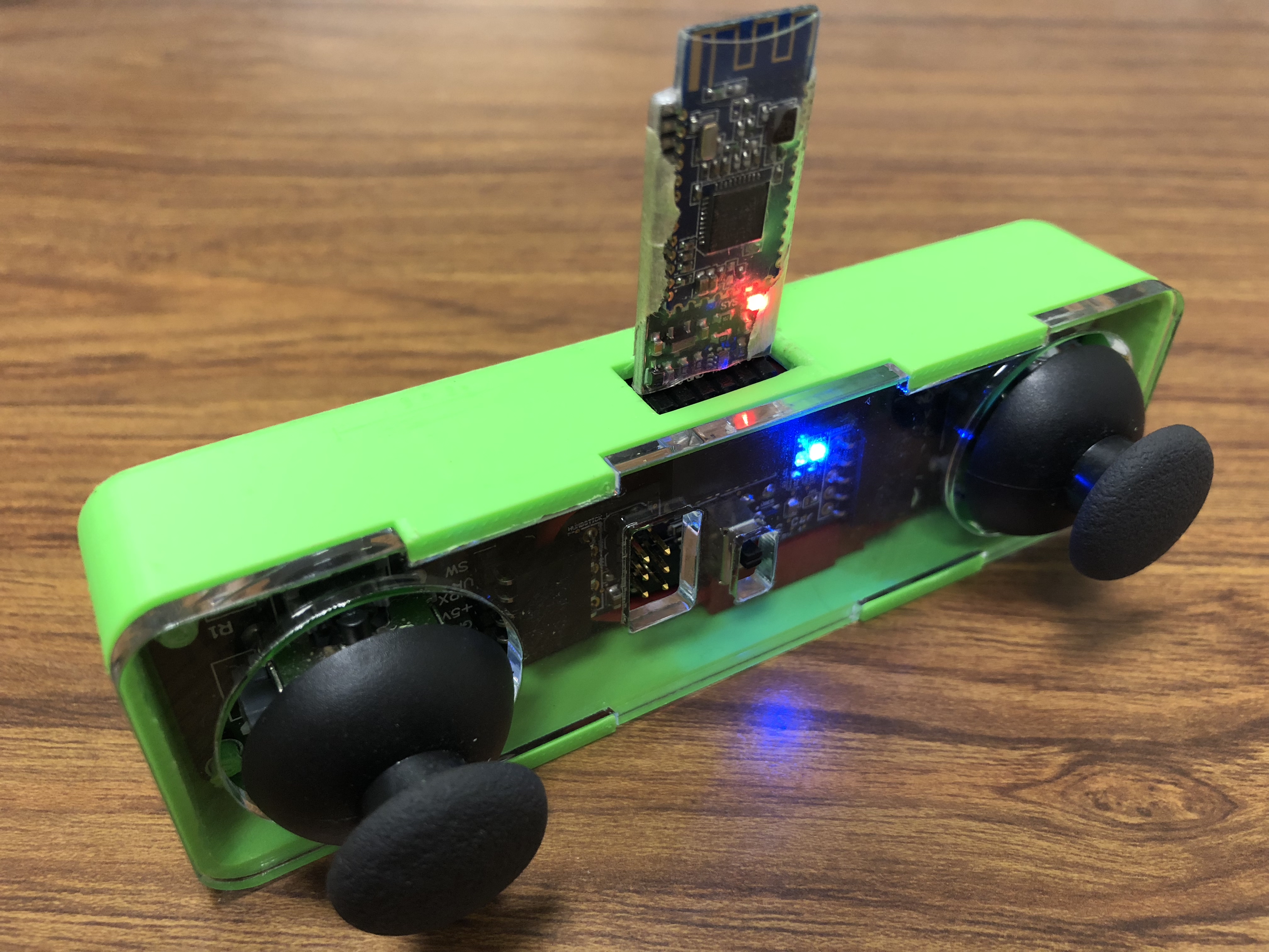
The remote hardware is extremely simple. It utilizes the very small ATtiny85 for its microcontroller (discussed further in the next section). Two thumbsticks (or joysticks) that control the throttle and degree of turn of the vehicle. Of course, it has its wireless module - the blutooth HM-10. We also have an LED attached to a PWM pin that can be used for debugging or anything you choose. The remote is powered by a 7.4V LiPo battery that is much larger than is necessary - it can last for weeks of play - because the remote consumes very little power. We use this LiPo battery so that it may be freely interchanged with the vehicle if necessary.
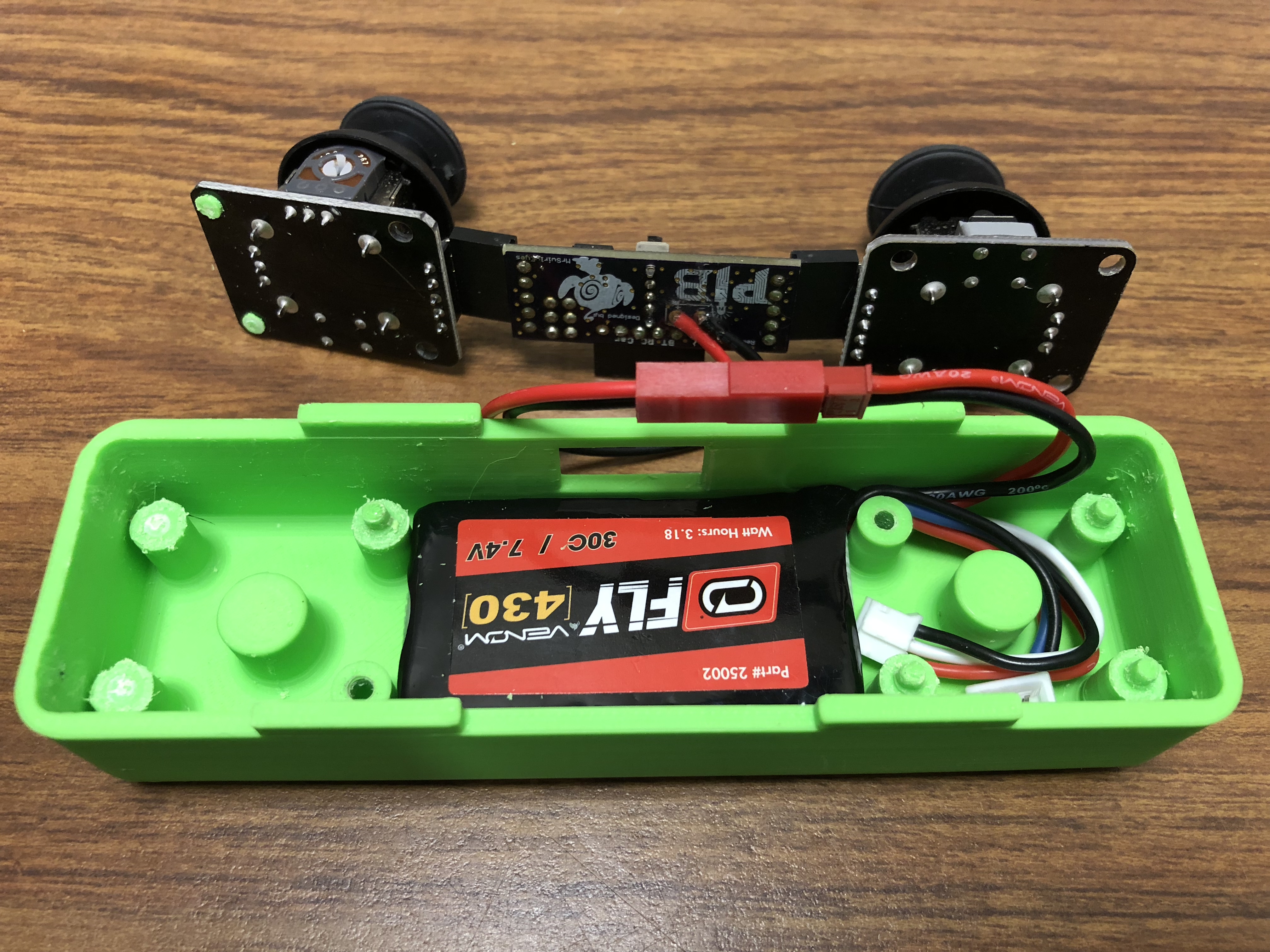
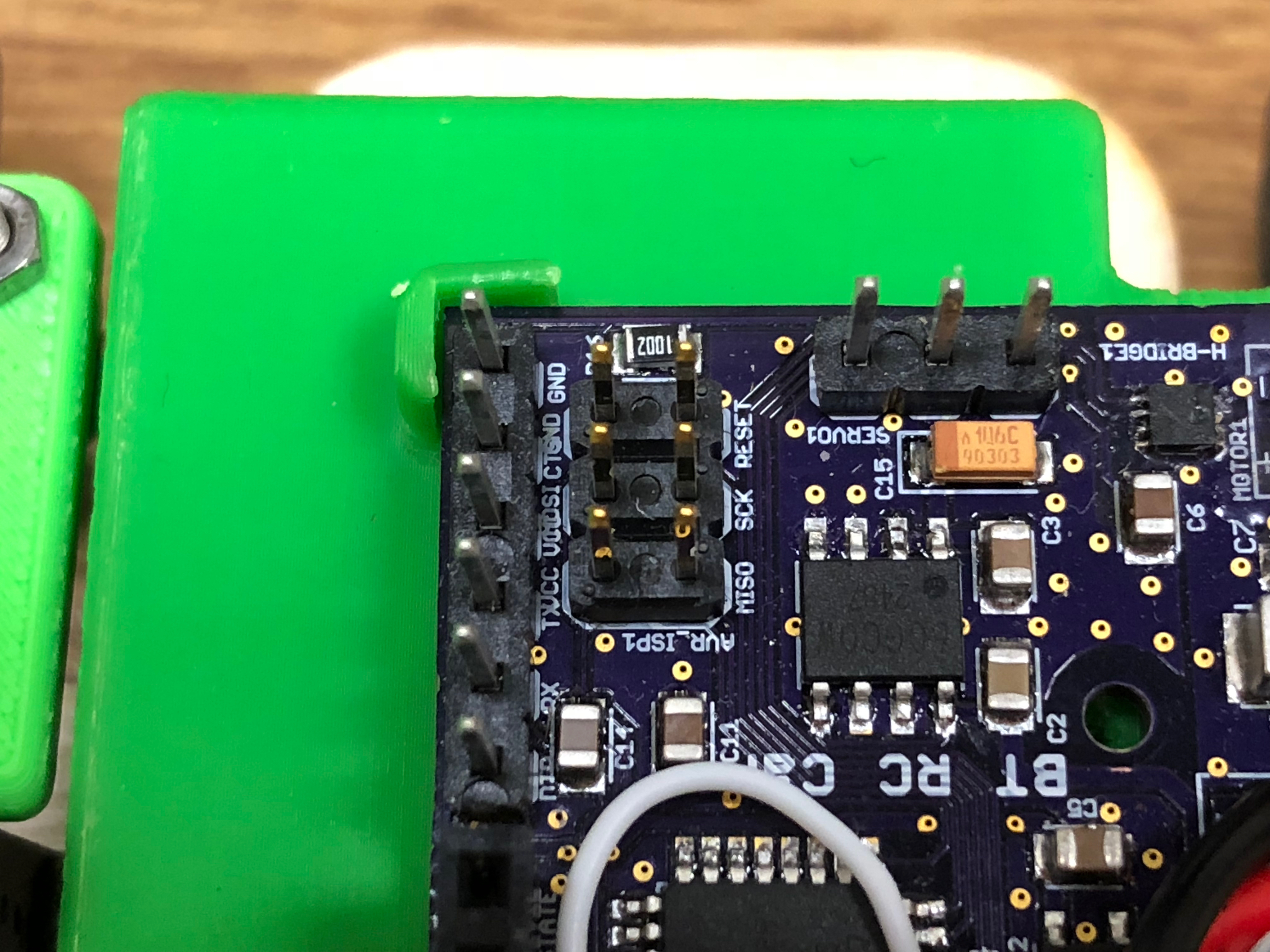
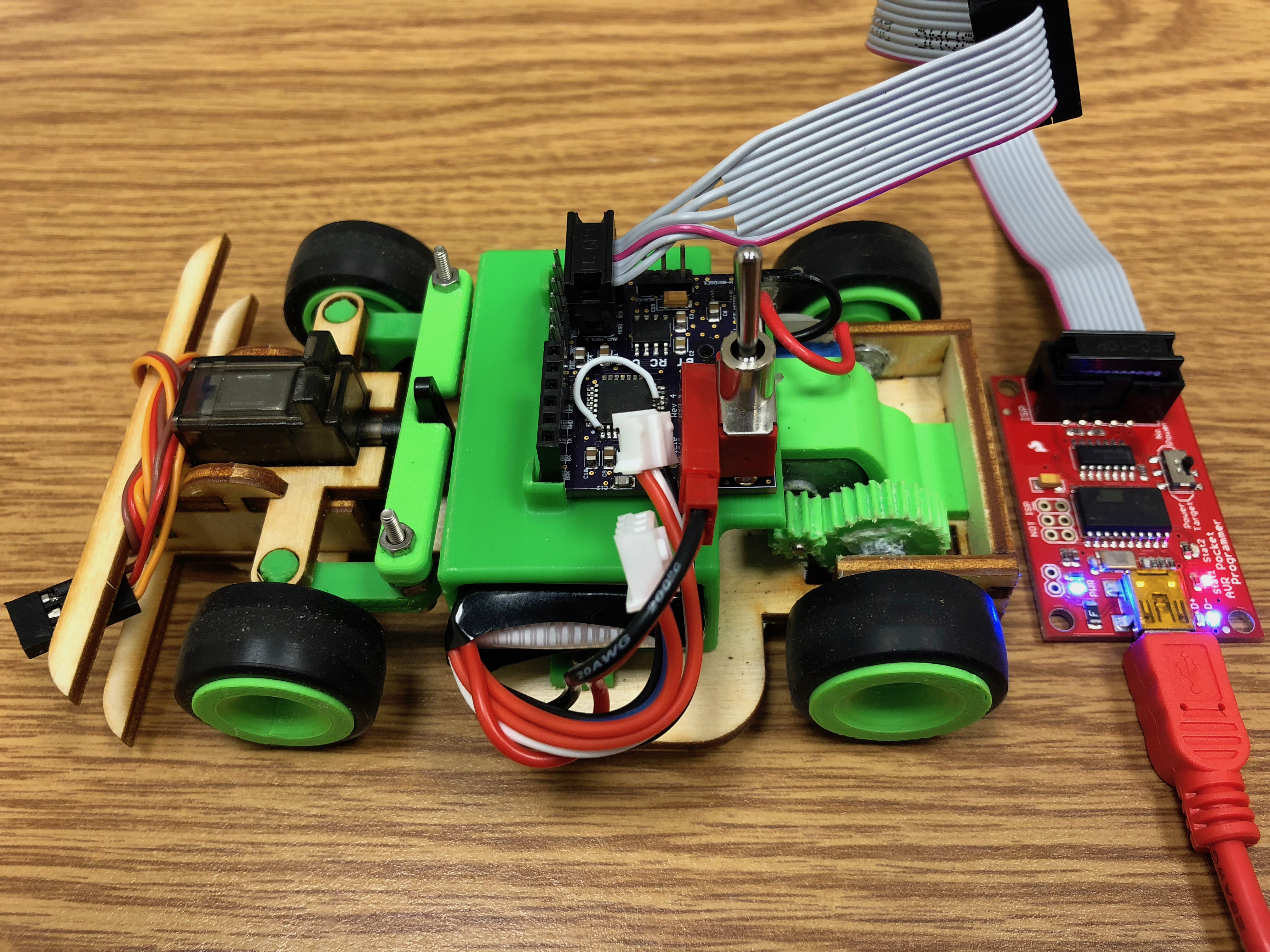
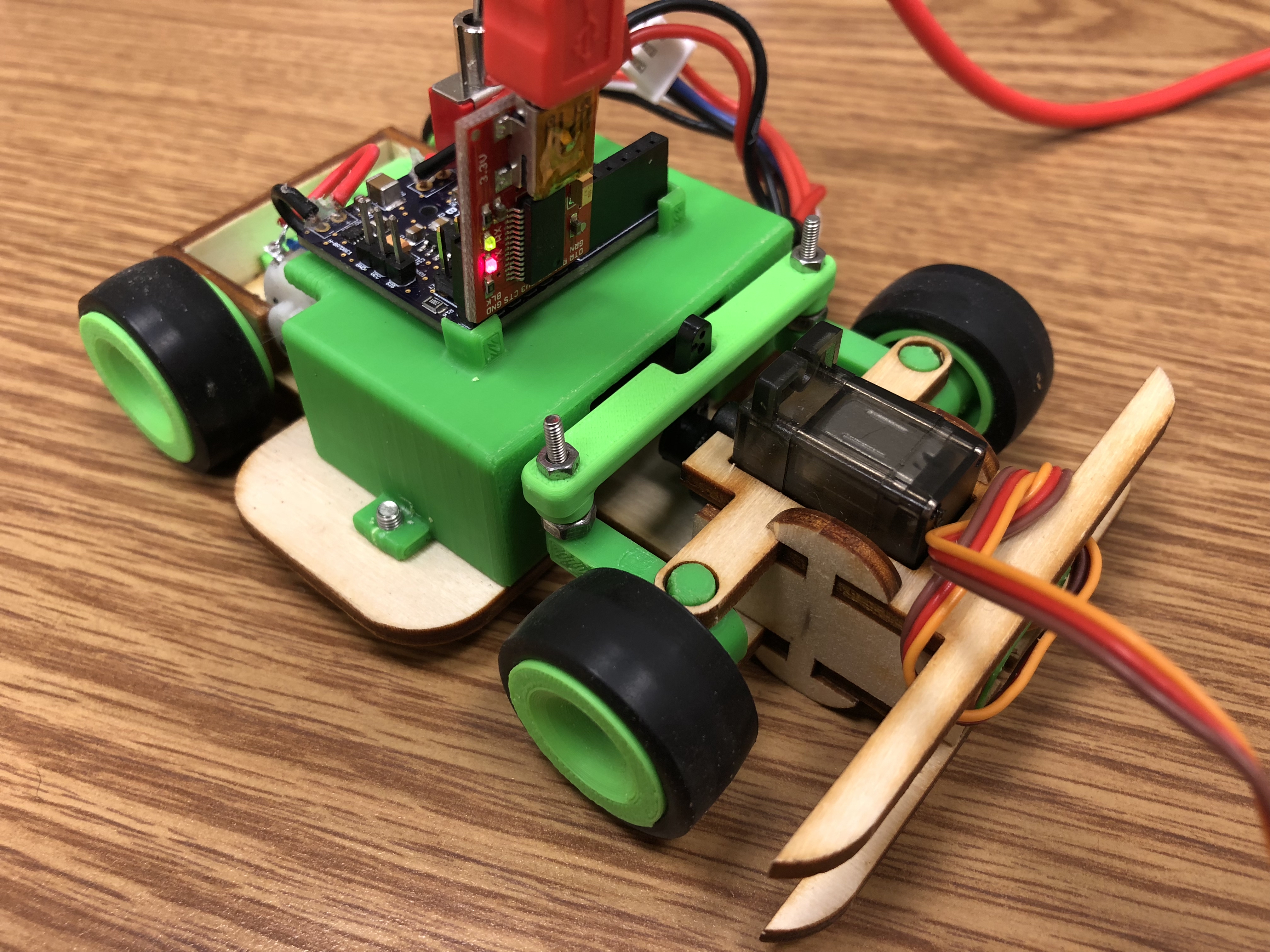
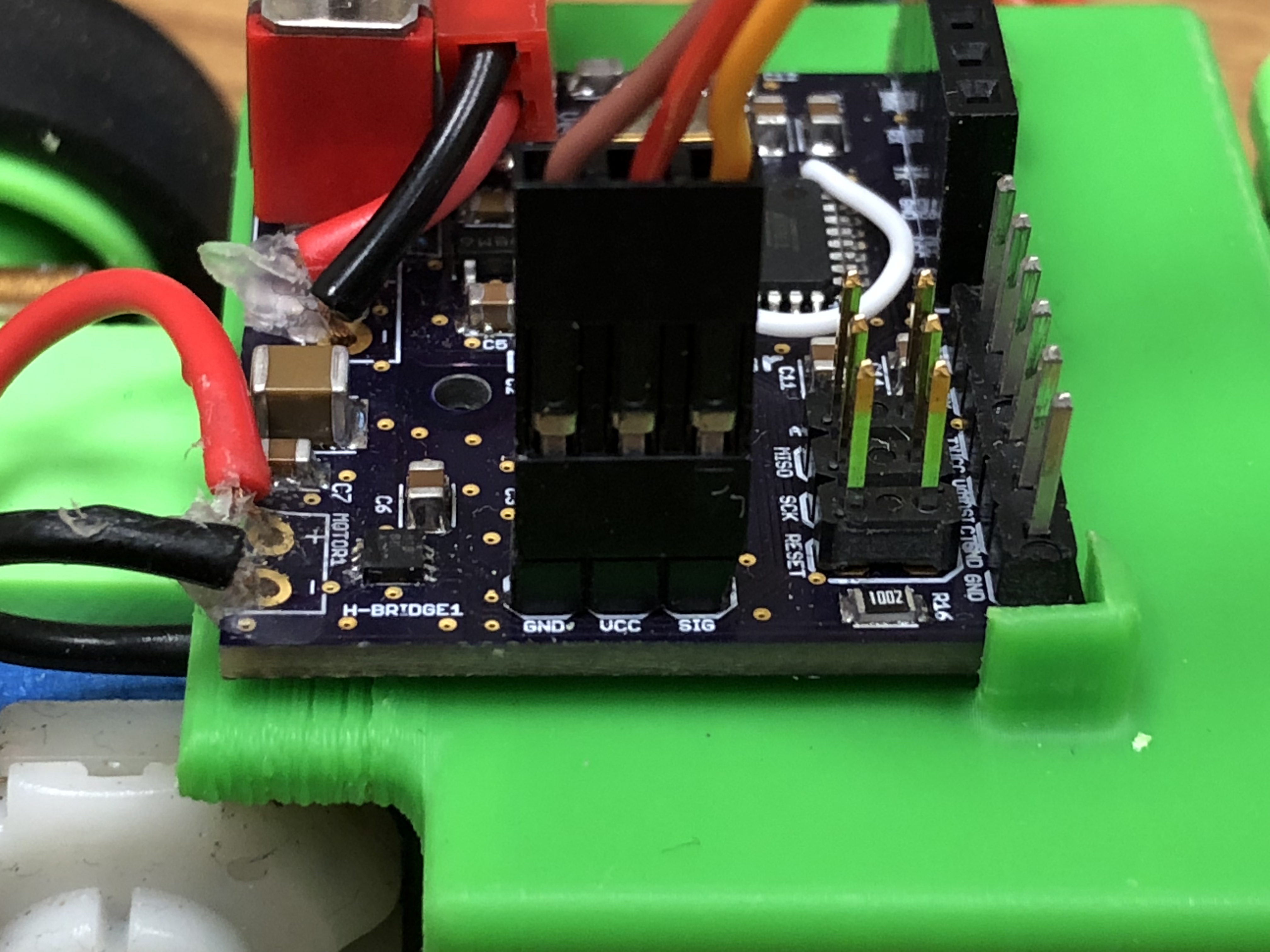
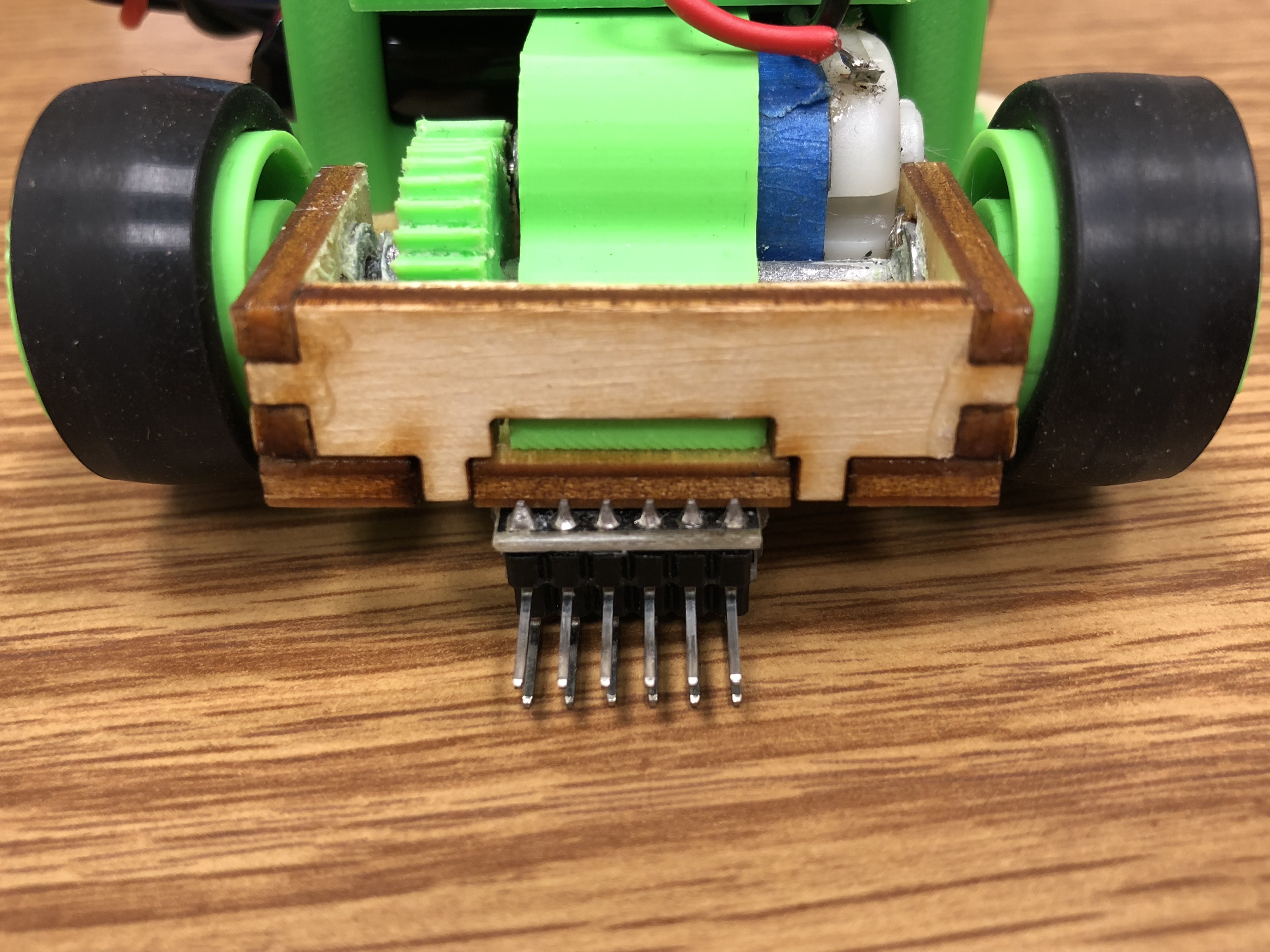
The vehicle hardware is not much more difficult, but it is doing more of the heavily lifting and consumes a lot more power. It uses the same microcontroller as the Arduino UNO - an ATMEGA328p (discussed further in the next section). It has a small, yet powerful, micro-servo that will turn the vehicle that is controlled with a single PWM pin. It also has a very small motor that is specified for speed - at the cost of very minimal torque. The motor is controlled by an extremely small H-bridge so that we may seamlessly move forward and backward using one digital pin for the direction (forward or backward) and one PWM pin for speed in the given direction. Of course, the vehicle has an identical HM-10 bluetooth. The remote is powered by the same 7.4V LiPo battery. The battery for the vehicle dies after a couple days of use - so pay close attention for a decrease in performance.
If you are a frequent maker using an Arduino or something of the like, then - unless you caught it - there are no Arduino development board attached to the remote or vehicle. An Arduino was used in the prototyping phase of this project, however we have replaced each Arduino with an appropriate AVR microcontroller so that our device is small and efficient in terms of design.
The remote sports an ATtiny85 microcontroller. A very small 8-pin device that is pales in performance as compared to the Arduino UNO's ATMEGA328p, however for the simplicity of our application - the remote - it is a perfect fit. All it has to do is use 2 analog pins to read from the thumbsticks and two pins that will act as a virtual UART (Universal Asynchronous Receiver-Transmitter). Unfortunately, one of the drawbacks of the ATtiny85 is that it does not have a dedicated UART - however, we will be using a virtual UART which is done through the default SoftwareSerial library that comes preinstalled with the Arduino IDE.
The vehicle rocks an ATMEGA328p microcontroller. This microcontroller is the exact same AVR microcontroller used on the Arduino UNO development board - except that we are using a smaller (surface mount) package. The use of the ATMEGA328p microcontroller may be over specified for our vehicle application, however it is still relatively cheap and works perfectly for our vehicle.
One of the advantages of using the AVR microcontroller familiy is the wide-support from the open source community on their use. Furthermore, SpencerKonde has created a powerful library allowing us to program the ATtiny85 (and pretty much any other ATtiny variant) using the Arduino IDE. The ATMEGA328p will be configured such that it is essentially a custom Arduino UNO board. Custom in that it is not a general development board - it is tuned to our BT RC Car Vehicle application.
One of the most interesting and exciting aspects of this project is the wireless communication between the remote and the vehicle. We will be using the HM-10 bluetooth module on both the remote and vehicle. Similar to using your computer or phone to pair to a bluetooth device, the bluetooth module on the remote and the vehicle each have to pair with each other. One of the bluetooth modules will play the role of master (or central) and the other will play the role of slave (or peripheral). For this project, it does not matter whether the remote or vehicle bluetooth device plays the role of master or slave; it is only for the pairing process that this is important. After we pair the devices together, we will be utilizing a feature of the modules such that they will automatically pair to each other as soon as both devices are powered and in range of each other.
As for the actual code to implement the one-way communication protocol, we will send information from the remote to the vehicle. The data that we will transmit will be each of the analog readings from the thumbsticks for our servo and throttle data. These data will be transmitted through the bluetooth to the vehicle and write the servo and H-bridge (which write to the motor). The explicit implementation for the degree of turn via the servo, max speed, and how we distinguish between moving forward and backward is up to You! For example, we could send a third piece of data that denotes direction, but it is not necessary with the implementation we have deployed - and we will share our thoughts, but ultimately this will be your BT RC Car.
Again, we want to stress that we can employ a two-way communication protocol - it is certainly possible. However, for this application it was not desired by our design. But You are more than welcome to utilize two-way communication in this project or for a potential modification. For example, maybe a battery monitor on the vehicle and when the LiPo battery voltage is too low, it can relay to the remote with some indicator - maybe the LED that is not really needed or a buzzer - that it is time to swap the battery.
Feel free to checkout our bluetooth tutorial for general details of two-way communication using the HM-10 bluetooth module. (Bluetooth HM-10 Tutorial)
The BT RC Car is a great example of a moderately challenging PCB project. We will be designing two boards - the remote PCB and the vehicle PCB. The area/size of a PCB board is usually proportional to price, so it is encouraged to make your PCB as small as possible.
The remote PCB was created to be as small as possible using 0805 (standardized package size) passive components and keeping components only one face of the board. The vehicle PCB needs a bit more care. We have a relatively power hungry and very noisy motor. The servo is a bit quieter, but is also a power hungry component. If special care is not taken to isolate the noisy components from the quieter digital components, there will be visible interference between the servo and motor (e.g. the servo will shudder when throttle is applied to the motor).
This may be an unfamiliar concept to have to worry about in most prototyping projects, but noise is a very real and common problem in industry and more complicated projects. It is (arguably) a better (but frustrating) learning experience to see this problem yourself and see your way through it. However, we want to deliver to you a working BT RC Car, so we will take this precaution even if we may not directly observe it during the project, so please take our word. :)
The progression of the project has an order, but some parts may be followed loosely. We organize this project in an order we believe makes the most sense. However there are some modules and components of the BT RC Car that can be done in parallel and out-of-order from what we have presented. Of course, depending how far out-of-order one goes, it may not easy to complete a given task (gap in learning), or bottlenecked from completing.
What we have imagined for the project slow is as follows. Start with an Arduino UNO and breadboard the majority of the project. That is, through a single Arduino UNO, read from the thumbsticks, write to the motor driver (motor + H-bridge) and servo - no wireless component yet. Then split off the hardware across two Arduinos and get the same concept working wirelessly using the bluetooth modules.
The next few steps can be done concurrently, however proceed with caution as the next few parts are things integrating together and there are a lot of inter-dependencies.
Then we introduce the ATtiny85, the (explicit) ATMEGA328p, and how we program these AVR microcontrollers. We will not explicitly breadboard with these, instead we will give the appropriate background and guidance to orient you to work on the PCB design component and integrate the aforementioned microcontrollers. With the exception of using the ATtiny85 and ATMEGA328p, we have breadboard everything - so knowledge of the PCB schematic should be straight forward to create from the breaboarded circuitry. We provide the PCB in the BT RC Car kit, however you are encouraged with the practice of this project to pursue PCB printing!
After the PCB design of the remote and vehicle, or concurrently, we turn to the 3D modeling using SolidWorks or your favorite 3D CADing software (e.g. OnShape, Autodesk Fusion360, etc.). This is possibly the most interesting and creative component of the project. Here we will show you our explicit design as an example, but we encourage you to add your own creativity. The challenge is visualization as you bring PCB to be fitted into your design. This is the epitome of the measure twice, cut once principle. It will also significantly develop or hone your technical prowess using these powerful prototyping tools - the same of which are used in industry. After the design, you make your cuts with a laser cutter or 3D print your design.
Another concurrent task is soldering. The PCBs we provide will work, it is just a matter of soldering it together correctly. Be very patient with soldering as it is a task you will want to get right the first time - fixing PCB mistakes can be a massive headache if you are not experienced.
Next, we have the real integration process. We have our laser cut and 3D printed chassis, and our soldered PCBs, time to put everything together to make the realization of the BT RC Car! One of the beautiful parts here is that You should already know how everything should fit together - we already designed how it should come together. It is seeing the visualization turn into a reality that is an exciting experience! Of course, there maybe some interesting pitfalls and that we why we provide the working examples.
Finally, it is time to bring the BT RC Car to life. We already coded the behavior of the BT RC Car in the prototyping phase, it is just a matter of making small refactors; mostly just pin number translation from Arduino UNO to ATtiny85, you can use the same pin configurations as the Arduino UNO for the ATMEGA328p - remember this is the Arduino UNO chip, just in a different package! Upload your code, fine tune any changes, and make your BT RC Car drive!
And that is it! Keep this module in mind as you progress through the project. You will be doing smaller tasks that will be introduced with generalized concepts. It is up to You to internalize the learning experience as you progress - so do not lose sight of the big picture!
Now, lets make fun!
In this and the next several modules, we will be breaking down the hardware we will use for the project one at a time and demonstrating how to get started. As we touch each, we will progress with the BT RC Car with challenges that ultimately leads to the development of the code we will deploy in our BT RC Car!
First, we will start with the thumbsticks! We will illustrate the hardware setup and demonstate some code to get started with the basics of the thumbstick. At the end of this module, there will be a challenge using the thumbsticks. The challenge is the development of the BT RC Car code, not some frivolous exercise.
The thumbstick, analog stick, or joystick (although when we think of joystick we imagine the arcade style - large ones that you use your entire hand to play with) is an analog device. It has two potentiometers, one for the X axis and one for the Y axis, that takes in a voltage across its VCC (labeled +5V) and GND pins. You can move the thumbstick in approximately 45 degrees in each axis direction from its resting state as well as any position as a function of both axes. As you move the thumbstick around the internal potentiometer's third pin behaves as a voltage divider constantly giving a voltage between GND and VCC.
Although the breakout thumbstick we are using is labeled +5V, it works just as well at 3.3V
If you press down on the head of the thumbstick it depresses until it actuates an onboard momentary push-button. This is the only digital component of the thumbstick. We will not utilize this push-button feature in the BT RC Car, however we show how to use it for completeness.
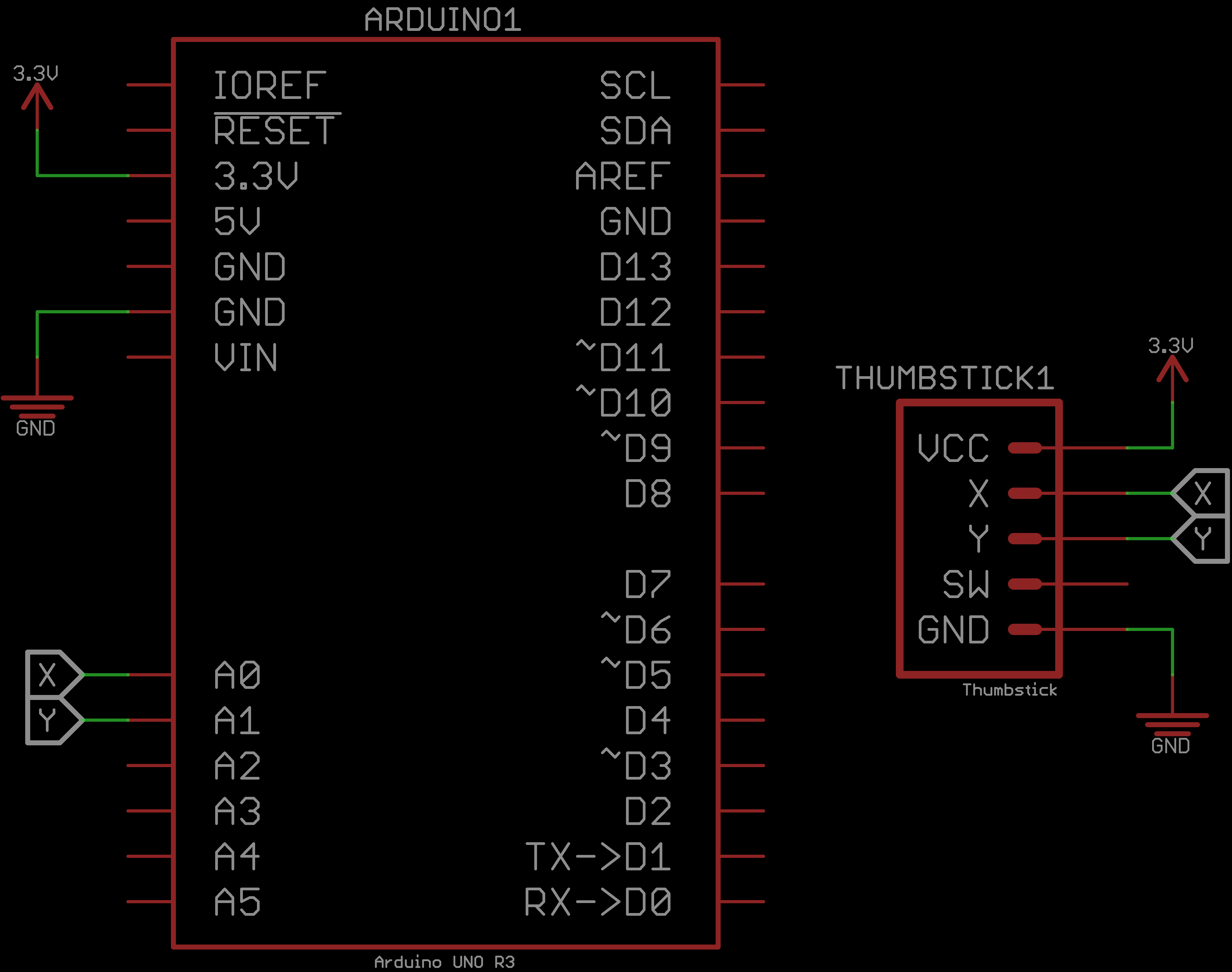
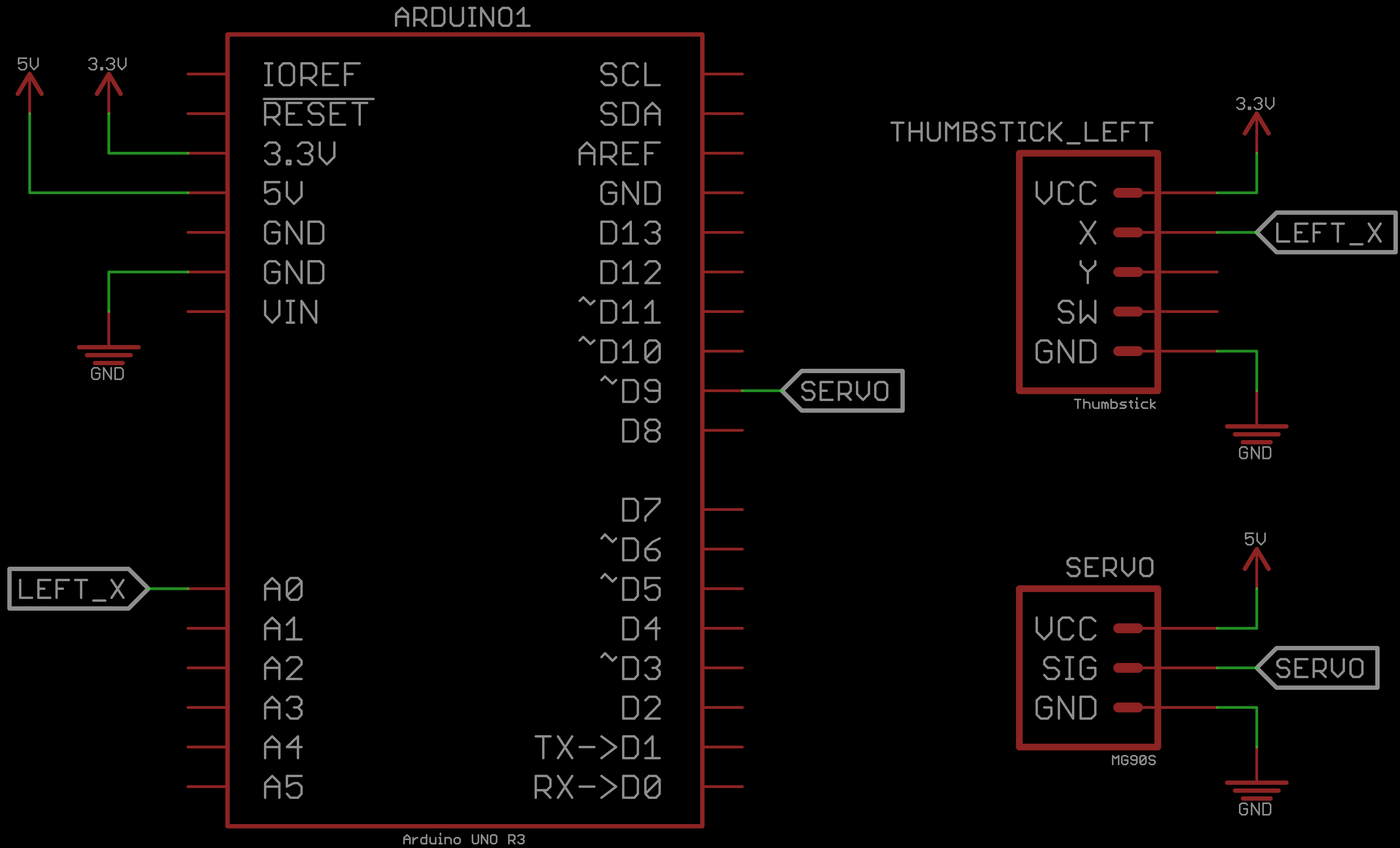
Let us make the circuit to play with the thumbstick. Construct the following circuit to connect the thumbstick to the Arduino UNO:
We are using 3.3V because these will ultimately be on the remote which will be operating at 3.3V
To test this module, we will use the following code:
// Program to test the thumbstick
//
// Prints the X and Y analog readings
//  and the state of the SW (push-button)
//  of the thumbstick to the Serial Monitor
//
//  Arduino to thumbstick connections
//  Arduino 3.3V or 5V to VCC of thumbstick
//  Arduino analog pin A0 to X pin of thumbstick
//  Arduino analog pin A1 to Y pin of thumbstick
//  Arduino digital pin 2 to SW pin of thumbstick
//  Connect GND from the Arduino to GND on the thumbstick


#define BAUDRATE 9600

#define thumbstick_x A0
#define thumbstick_y A1
#define thumbstick_sw 2

int raw_analog_reading;
int switch_state;

void setup() {

  // Start Serial Monitor for feedback
  Serial.begin(BAUDRATE);

  // Configure with internal pull-up resistor
  //  so we do not need a physical pull-down resistor
  pinMode(thumbstick_sw, INPUT_PULLUP);
}

// Continuously print the X and Y analog readings
//  and the state of the push-button of the thumbstick
void loop() {
  Serial.print("(X,Y,isPressed)=");

  Serial.print("(");

  // Read + print thumbstick X
  raw_analog_reading = analogRead(thumbstick_x);
  Serial.print(raw_analog_reading);

  Serial.print(",");

  // Read + print thumbstick Y
  raw_analog_reading = analogRead(thumbstick_y);
  Serial.print(raw_analog_reading);

  Serial.print(",");

  // Read + print thumbstick switch state
  //  Note: We invert the reading because of the internal pullup resistor
  switch_state = !digitalRead(thumbstick_sw);
  Serial.print(switch_state);

  Serial.println(")");

  delay(10);
}
This code is straight forward, it simply prints each of the analog values from the thumbstick for both the X and Y axis. It also prints the status of the onboard push-button. We are using a feature of the Arduino UNO that the pin of the microcontroller than employ its own internal pull-up resistor. Thus, when the button is not pressed, it will return a logic level HIGH value until pressed; then returns a logic level LOW value until released. We invert (!) the state when we perform the digitalRead from the switch so that it feels more intuitive to the user.
An example of the code running:
Playing with the thumbstick should feel intuitive. The digitalRead from the button constantly prints a 0 until you press the button, and then prints a 1 until released. The printing of the analog X and Y values will show a clear minimum and maximum value. At rest, that is without moving the thumbstick, the analog readings should be at some steady-state value with should be approximately half of your maximum analog reading.
The onboard ADC of the Arduino UNO has a 10-bit resolution, thus we get 210=1024 steps of analog voltage readings from the thumbstick potentiometers that range from GND to VCC. These readings are mapping GND through VCC to 0 through 1023. If you are using VCC=5V, you may get the full range of the ADC - that is, you may see a minimum value of 0 and a maximum value of 1023. If you are using VCC=3.3V (as shown in the GIF above), then you may observe that you never reach the full range of the ADC. This is because the ADC is voltage reference is with respect to 5V. This is not a bad thing that we miss out on some resolution, it will work just fine.
We have 1024 steps of resolution, but since we start at zero, the range of values is from 0 to 1023
Observe, if using VCC=3.3V, the maximum value may be approximately 700, which is approximately ⅔ of 1023 which should make sense because 3.3V is be approximately 700, which is approxi of 5V!
You may have observed that, depending on the orientation in which you are holding the thumbstick, which direction - relative to the thumbstick - increases or decreases the analog readings to reach your minimum and maximum. It may even feel backwards or upside-down from your expectations. This is no problem, we will address this in an exercise!
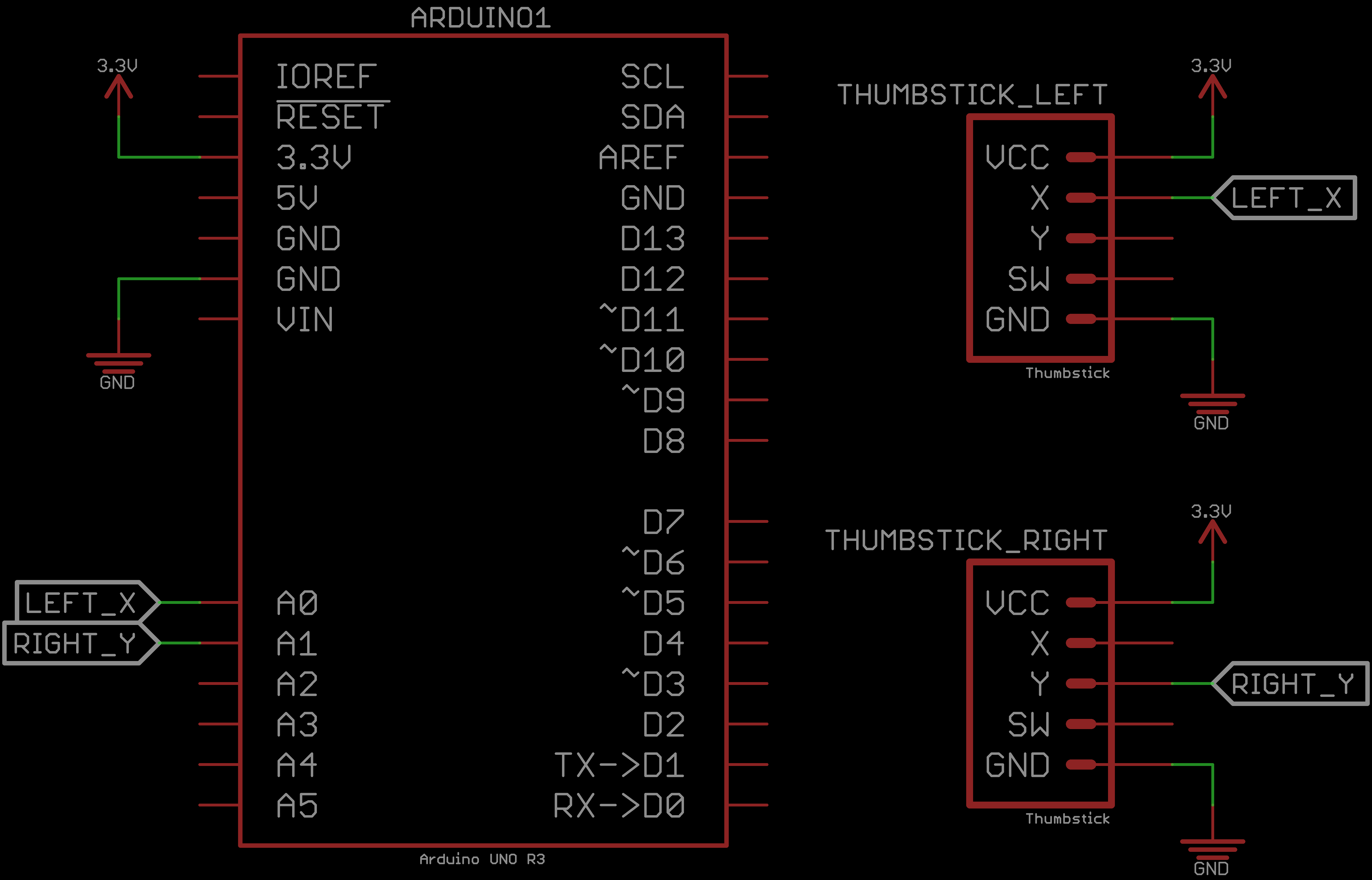
In this challenge, we are essentially forming the basis for the remote. Looking ahead, we will have two thumbsticks that control the motor and servo. The hardware setup is similar as shown earlier, except we are not interested in the push-button and we only want to use one of the analog pins from each of the thumbsticks. For one of the thumbsticks use the x-axis potentiometer (later will control the steering) which we will refer to as the steering thumbstick, and for the other thumbstick use the y-axis potentiometer (later will control throttle) which we will refer to as the throttle thumbstick. As for which side (left or right - like most gaming controllers) you want the throttle or steering thumbstick on is up to you.
Further specifications include the following. For your steering thumbstick, regardless of what side it is on (left or right in physical placement), when you actuate the steering thumbstick head LEFT it should print out the minimum analog reading that your thumbstick produces (e.g. 0 or something close). When you actuate the steering thumbstick head RIGHT it should print out the maximum analog reading that your thumbstick produces (e.g. likely in the range of 500-1023).
For the throttle thumbstick, we do essentially the same thing. When you actuate the throttle thumbstick head DOWN it should print out the minimum analog reading that your thumbstick produces and when you actuate the throttle thumbstick head UP it should print out the maximum analog reading that your thumbstick produces.
The X printout comes from the first thumbstick when actuating LEFT and RIGHT; and the Y printout comes from the second thumbstick when actuating UP and DOWN. The behavior of your code should simulate the something similar to the GIF below. In this scenario we chose the left thumbstick to be our steering thumbstick actuating LEFT and RIGHT. Similarly, we chose the right thumbstick to be our throttle thumbstick actuating UP and DOWN.
Note that this solution is NOT the only solution. This is just how we realized it. It should look almost exactly the same as the code we started with when testing the thumbstick. The only difference is the removal of the push-button code, and that we have two physical thumbsticks as opposed to one.
The schematic should be similar to as follows:
Again, the code can vary, but here is what we have for our solution:
Hopefully this challenge was not too difficult, this was meant to be very simple - after all, we just started. As we progress through the BT RC Car project, the challenges will get increasingly more difficult. However, we are taking things step-by-step, so pay attention to the increasing difficulty gradient, versus dumping a bunch of requirements and specifications and expecting the same results at the end. Taking a problem and breaking it down into these smaller steps is a valuable skill - especially for teaching others (hence this project page).
In this module, we turn our attention to the servo. The servo is a part of the vehicle. We will use our Arduino UNO to control the servo alone. Then in our challenge at the end of the module we will start to add on to our code such that the steering thumbstick will control the servo. It will feel like the remote is controlling the steering of the vehicle. Let us get started.
The servo is a powerful device. Unlike the thumbstick, a sensor; the servo is an actuating device. Servos are digital devices, which means it receives 0's and 1's to function. But when we write to servos there is a degree at which we want a servos poition to change to. The way this is accomplished is through a PWM (Pulse Width Modulation) pin on the microcontroller to control the position of the servo (generally between 0 and 180 degrees). Although the the servo is a digital device, the method by which we control the servo is considered an analog method to the Arduino - that is, we send a signal of a particular width (logic level HIGH for a set amount of time) using the analogWrite function.
The Arduino UNO produces a PWM signal with 8 bits of resolution (28=256). This allows us to write various steps to a PWM driven device. Arduino has a built in Servo library that takes care of the heavy lifting. It gives support of creating the waveform and all we have to worry about is to what degree we wish the servo to turn to between 0 and 180 degrees.
If we have a simple circuit, we can generally get away with powering the servo with the Arudino UNO onboard 5V rail. However, if we had several servos or the servo was working under a heavy load it may not operate well through your computer's USB port limited at 500mA. Servos can be power hungry devices if they are actuating quickly or under a heavy load. They can also become noisy and get hot under these conditions. For this module, we are OK to power the servo through the Arduino 5V rail, however when we make the actual BT RC Car, we want our servo to be delivered with sufficient power.
In general most digital servos have three colored wires: red, black, and white or orange:
The circuit for the servo is as follows:
You may use any pin you want, just make sure it is a PWM pin (signified by the tilde).
We recommend using pin 5 for the servo because the PCB we created for the BT RC Car Vehicle is connected to pin 5.
If your servo is jittery or your observe the LEDs onboard the Arduino UNO flickering when the servo moves, you may need a dedicated power supply because your servo is not powered adequately through your computer USB port and the Arduino onboard 5V regulator. We recommend putting up with the jittering until we get to the PCB.
To test the servo we use the following code:
// Program to test the servo
//
// Prints the position of the servo
//  and sweeps from 0 to 180 degrees
//  and sweeps back from 180 to 0 degrees
//
//  Arduino to servo connections
//  Arduino 5V to VCC (red wire) of servo
//  Arduino digital PWM pin 9 to SIG (orange or white wire) of servo
//  Connect GND from the Arduino to GND (black wire) of the servo


// Import Arudino's Servo library
#include <Servo.h>

#define BAUDRATE 9600

#define servo_pin 9

Servo servo;

void setup() {

  // Start Serial Monitor for feedback
  Serial.begin(BAUDRATE);

  // Attach servo pin to Servo object
  servo.attach(servo_pin);
}

void loop() {

  // Sweep from 0 to 180 degrees
  for(int i = 0; i <= 180; i++) {
    Serial.print("position=");
    servo.write(i);
    Serial.println(i);
    delay(5);
  }
  delay(500);

  // Sweep from 180 to 0 degrees
  for(int i=180; i >= 0; i--) {
    Serial.print("position=");
    servo.write(i);
    Serial.println(i);
    delay(5);
  }
  delay(500);
}
The code is the typical servo sweep code that comes as an Arduino example sketch. It continuously sweeps between 0 and 180 degrees.
An example of the code running:
You do not need to attach the servo horn yet, we have it attached so it is easier to see the actuation process.
The GIF is perfectly in sync, but you may notice the servo horn stops moving but the code is still writes about 10 more degrees. This may happen to you as well, it is because this servo happens NOT to be moving the full 180 degrees. This is typically bad for a servo (you may hear some strenuous noises). We will tune this later, however we encourage you to do it now!
In this challenge, we will use the steering thumbstick to control the servo. As we actuate the thumbstick from left to right, record the minimum and maximum attainable values. We recommend using a variable to record these minimum and maximum values. Similarly, define variables for the minimum and maximum value we want to write the servo to - when we put together the BT RC Car, we may want to narrow the range from 0 to 180 degrees.
Next, we want to map the 10 bit (1024 steps) analog readings from the thumbsticks to the the 8 bit (256 steps) pwm signals for the servo. Arduino has an extremely useful function called map that will map one domain to another. With the mapped value, we can write this to the servo and we will be able to move the thumbstick left and right and see the servo move left to right as well.
If the mapping was done well, then when the thumbstick is at rest it should be within 2-3 degrees from being 90 degrees, which is our center and how our future BT RC Car will move straight.
We will show the solution with code only relevant to the challenge, however feel free to build atop your code - eventually the code we build from module to module will be your BT RC Car code!
It is not necessary to have printouts, however we include them here for illustration. This is the kind of behavior you want to emulate:
Note that this solution is NOT the only solution. This is just how we realized it. Pretty much we fused the thumbstick challenge with the servo example code. The interesting part that we have added that is a bit different is the Arduino map function. It is a very useful method to use for all kinds of applications. We will use it again soon. We also added the minimum and maximum value variables. This is extremely effective to do in all sorts of applications - especially if these kinds of numbers are used more than once. It is common to have these constraining variables, and most people will put them hardcoded (just the number in the function), but making a variable for it allows us to change all instances at once and not have to scroll through out code to make the change, instead we have levers or knobs at the top of the code in which we tune our code in a very clean manner. The pitfall of this is that our code may get longer and look more cluttered - we probably should have used shorter variable names.
The schematic should be similar to the following:
If your servo is jittery or your observe the LEDs onboard the Arduino UNO flickering when the servo moves, you may need a dedicated power supply because your servo is not powered adequately through your computer USB port and the Arduino onboard 5V regulator. We recommend putting up with the jittering until we get to the PCB.
Again, the code can vary, but here is what we have for our solution:
We have the workings of half of a wired remote. Next up, we need to add our motor driving circuitry and then control it with the thumbstick so we can control the throttle!
In this module we will explore the motor driver circuitry that will drive our BT RC Car. The motor driver is comprised of two parts: the motor and the driver. The motor is small and does not have much torque, but will be able to carry our BT RC Car and make it zippy. The driver will allow our motor to turn its shaft in either direction - forward and backward.
Together the motor driver + the servo will give us the functionality of a typical vehicle. We have control via the thumbsticks. At the end of this module and its challenge we will have this basic functionality of a car.
The motor operates via a current that energizes a thin electromagnet that generates an electric field. There is a permanent magnet surrounding the electromagnet which attracts and repels the electromagnet. This causes the electromagnet to spin. As it spins, the polarity from the power source is flipped via brush contacts, which perpetuates the spinning. The shaft of the motor spins with the electromagnet which is what we will observe as the motor actuating.
Looking forward, we will attach a pinion gear to the shaft of the motor which will drive a larger gear attached to an axel that will drive the back wheels of the BT RC Car. The front wheels are controlled by the servo which gives us full control over the vehicle.
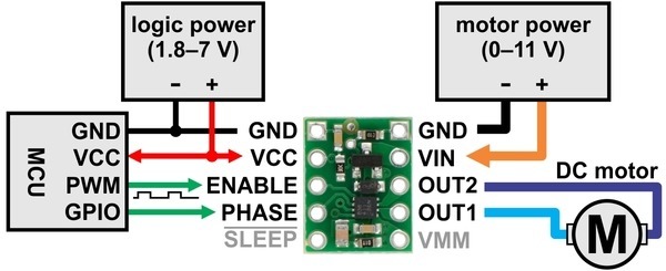
The driver is an H-bridge. An H-bridge is essentially a device that allows us to control the direction of current through two pins. These two pins will be connected to the motor, so we can effectively drive current in either direction and our BT RC Car will be able to move forward and in reverse. The H-bridge pins are referred to as the enable and phase. The phase pin determines the direction. A digital HIGH corresponds to one direction and a digital LOW corresponds to the opposite direction. The enable pin is the the magnitude of power, or speed, in the given phase direction.
To power the H-bridge, we give two power sources: one power source is our microcontroller digital logic signals, the other power source is across the H-bridge pin that powers the motor. We will be using the Arduino UNO to power the motor for now, but will use a LiPo battery later to make our BT RC Car fast.
We will be using a breakout board for the DRV8838 H-bridge which looks and operates as follows:
The motor does not look like anything special, small and cheap DC brushed motor:
The circuit to test the motor driver is as follows:
Observe we show that we are using a LiPo battery in this schematic. Feel free to use the LiPo battery to power the motor. You may also use a benchtop power supply. However, you can also use the Arduino 5V pin which will cause decreased performance, but at this point we are just prototyping with the hardware and it is OK.
To test the motor driver circuitry, we will use the following test code:
// Program to test the motor driver circuitry
//
// Prints the phase (direction) and enable (speed) of the motor driver
//  Ramps up to max speed, then slows down, in one direction
//  Ramps up to max speed, then slows down, in opposite direction


#define BAUDRATE 9600

// Motor Driver variables
#define enable 5
#define phase 6
#define FORWARD HIGH
#define BACKWARD LOW
#define THROTTLE_MIN 0
#define THROTTLE_MAX 255

void setup() {
  // Start Serial Monitor for feedback
  Serial.begin(BAUDRATE);

  // Set phase (digital) pin as an output
  pinMode(phase,OUTPUT);

  // Set initial condition for motor driver
  digitalWrite(phase,FORWARD);
  analogWrite(enable,0);
}

void loop() {
  // Sweep motor at phase = FORWARD,
  //  and motor speed at enable steps 0 to 255
  //  speed up
  digitalWrite(phase,FORWARD);
  for(int i = THROTTLE_MIN; i <= THROTTLE_MAX; i++) {
    analogWrite(enable,i);
    Serial.print("(phase,enable)=(");
    Serial.print(FORWARD);
    Serial.print(",");
    Serial.print(i);
    Serial.println(")");
    delay(5);
  }
  delay(500);

  // Sweep motor at phase = FORWARD,
  //  and motor speed at enable steps 255 to 0
  //  slow down
  for(int i = THROTTLE_MAX; i >= THROTTLE_MIN; i--) {
    analogWrite(enable,i);
    Serial.print("(phase,enable)=(");
    Serial.print(FORWARD);
    Serial.print(",");
    Serial.print(i);
    Serial.println(")");
    delay(5);
  }
  delay(500);


  // Sweep motor at phase = BACKWARD,
  //  and motor speed at enable steps 0 to 255
  //  speed up
  digitalWrite(phase,BACKWARD);
  for(int i = THROTTLE_MIN; i <= THROTTLE_MAX; i++) {
    analogWrite(enable,i);
    Serial.print("(phase,enable)=(");
    Serial.print(BACKWARD);
    Serial.print(",");
    Serial.print(i);
    Serial.println(")");
    delay(5);
  }
  delay(500);

  // Sweep motor at phase = BACKWARD,
  //  and motor speed at enable steps 255 to 0
  //  slow down
  for(int i = THROTTLE_MAX; i >= THROTTLE_MIN; i--) {
    analogWrite(enable,i);
    Serial.print("(phase,enable)=(");
    Serial.print(BACKWARD);
    Serial.print(",");
    Serial.print(i);
    Serial.println(")");
    delay(5);
  }
  delay(500);
}
The code appears long, but the print statements are most of its volume. The print statements are not necessary either, they are just for illustration and potential debugging. Observe the several #defines we have at the top of the code, these are for tuning later. For example, FORWARD is assigned HIGH, but after we construct the BT RC Car, it may (coincidentally), be that this will be in the backward direction, so we can tune this later as appropriate. It also saves our code from these random looking numeric constants. By making a variable (or #define), we make the code more readable.
There are four loops in this program, and they practically all function the same. In the first loop, we are increasing the motor speed from 0 to 255 in a the directio labeled as forward. In the second loop, we decrease speed in the same forward direction until the motor stops. In the third and fourth loop, we mimic the same behavior as the first and second loop, except the motor operates in the opposite, reverse, direction.
When we construct the BT RC Car and integrate the motor, the explicit direction of forward and backward may change depending on the connections made with the H-bridge and the orientation of the motor. Thus, we are using explicit variables to make this a simple change later.
The behavior of this program is illustrated as follows:
Similar to the last module with the servo, we challenge you to control the motor driver with the thumbstick. However, there is a catch! When the throttle thumbstick is pitched forward (up), we want the motor to move forward (again, this forward is relative - for now). When the throttle thumbstick is pitched backward (down), we want the motor to moev backward. And, when the thumbstick is at rest we want the motor to not move at all.
Now if you experienced from the last few modules, or have used analog sensors in other projects. They tend to be a bit noisy or jittery in their analod readings. We have also experienced them having drifted slightly from day to day, or week to week. So we cannot use just a single value for the thumbstick at the rest position and expect the motor driver to not operate. We need a dead zone, that is a threshold for which within some tolerance the thumbstick analog readings will stay in this dead zone reliably. Then once exceeding some threshold in the forward direction, the motor driver will drive forward. Similarly, once exceeding some threshold in the backward direction, the motor driver will drive backward.
The threshold tolerances that you choose should be a few points above and below the resting throttle thumbstick analog reading.
We will show the solution with code only relevant to the challenge, however feel free to build atop your code - eventually the code we build from module to module will be your BT RC Car code!
It is not necessary to have printouts, however we include them here for illustration. This is the kind of behavior you want to emulate:
The behavior should be similar to the following:
Note that this solution is NOT the only solution. This is just how we realized it. Pretty much we fused the thumbstick challenge with the motor driver example code. Again, we have utilizing the Arduino map function to map the analog throttle thumbstick readings into a range for forward and a range for backward to be written to the motor driver. We keep adding several variable constants to define the threshold, minimum, and maximum values to make modifying the code easy and accessible at the top of the program.
The schematic should be similar to the following:
Again, the code can vary, but here is what we have for our solution:
Next up, we are going to combine this exercise with the steer thumbstick + servo challenge to get the functionallity of an RC Car that is wired - that is, without the wireless bluetooth connections - yet!
In this challenge, we combine the work of the last two challenges. That is controlling the servo with the steer thumbstick and controlling the motor driver with the throttle thumbstick. If you have been building atop of your code, you may already have this functionality complete. If you have not, then it really should be an exercise of fusing the code from these two challenges together into a single program.
With the completion of this challenge you should have the behavior of an RC Car - just wired, no wireless component yet.
However, this challenge contains a special problem that you may run into - we certainly did. When you complete this challenge, you may run into a massive problem that will appear to have ruined your BT RC Car in the making. This may have been a problem you have run into if you have built other projects, and we are addressing it here: noise.
The completion of this challenge yields the following behavior:
If you observe carefully, you will see every time we active the motor, the servo acts erratically. When I actuate the servo alone, it seems to be behave as expected. However, when I actuate the motor, the servo always slams to one side and becomes stuck - even if I wriggle the steer thumbstick around, there is no response. This is because the motor is extremely noisy and is wrecking havoc on the rest of servo and the rest of the circuitry.
Unfortunately, it would seem our project must halt here. And in terms of prototyping and explicitly using a breadboard - this is the sad truth. However, it is time to learn a new skill: Printed Circuit Board (PCB) design. A PCB can fix this problem. And as we will get to, there is a few elements of PCB design that will fix this problem: a GND plane, spatially closer circuitry, isolating GNDs and noisy components, and better electrical connections.
If you have never heard of GND planes, that is OK, but these low-impedence GND connections clean up a lot of noise in your circuitry. Using the breadboard wires for power and GND buses, these are still terrible connections.
Spatially locality helps a lot, if your circuit is like ours - very neat with wires cut to size - then you are helping your circuit, versus having long jumper wires for making breadboard connections that are approximately a centimeter or two away. When we create the PCB, everything will be very closer together - the vehicle board will be smaller than the Arduino UNO board.
Isolating grounds could help on your breadboard circuit, but without the assistance of power planes - you will probably not notice any improvements.
Finally electrical connections. Jumper wires have a very small connection surface area, and in combination of all the above makes for terrible electrical conductivity. We will largely use surface mount components which have superior surface area contact.
A combinational improvement of all these factors in our PCB will grealt improve the performance of our BT RC Car.
So if you are having this noisy issue right now it is OK - we are having it too! We did not purposely make this happen to illustrate a point, this really happens to us too. So for this challenge, implement the behavior that is expected, and whether you have the noise issue, or not, the challenge exercise is still building atop what our BT RC Car code.
Note that this solution is NOT the only solution. This is just how we realized it. As we mentioned in the challenge specification. It is just a fusion of the steer thumbstick + servo challenge with the throttle thumbstick + motor driver challenge.
It is OK if you have the noise problem with the servo and motor interfering! There is no fix for this unless we use different hardware or until you make the PCB!
The schematic should be similar to the following:
Again, the code can vary, but here is what we have for our solution:
Nothing special here. Really is a copy-paste of the steer thumbstick + servo challenge and the throttle thumbstick + motor driver challenge.
Next up, we take a break from the circuitry that - literally - drives our BT RC Car and we will turn our attention to the HM-10 bluetooth module!
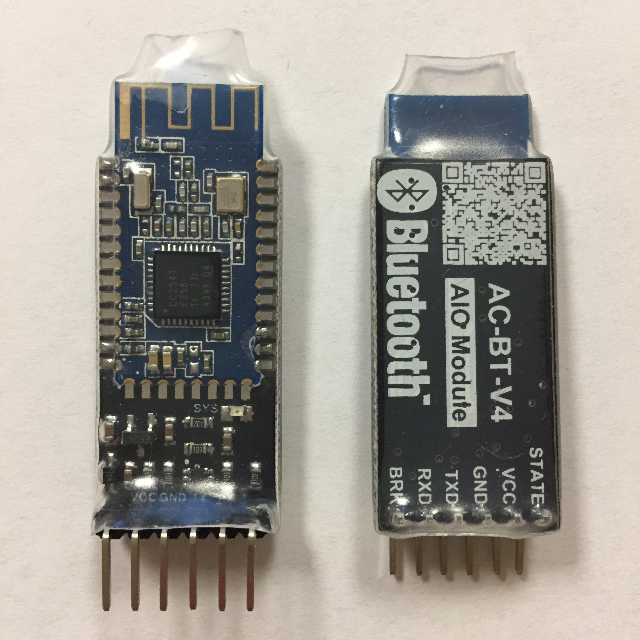
In this module, we turn our attention to the HM-10 bluetooth module. The bluetooth module will enable us to communicate between two Arduinos wirelessly. We have already seen the remote controlled part of the BT RC Car in action. As you might expect, we will learn how to use the bluetooth module and then integrate the bluetooth into our existing code.
With the addition of the bluetooth we will have the proof of concept of the BT RC Car complete. We will be able to wirelessly communicate from one the remote set (Arduino + thumbsticks) to the vehicle set (Arduino + motordriver + servo). Unfortunately, we will not have the chassis of the car complete yet so we will not be able to see any real action. Furthermore, we will still have the same noise problem. This will not be fixed until the end when we use the custom PCBs.
Let us get started with the bluetooth!
We have a tutorial already created for how to use the Bluetooth HM-10 module in general. So, instead of transcribing everything in that tutorial here, we will simple direct you to the tutorial.
The Bluetooth HM-10 tutorial is linked here: Bluetooth HM-10 Tutorial. Your task is to go through the following modules:
We give working of examples on how to use the HM-10 module. As you progress, think of how we will tie this into the BT RC Car. It is also important to understand the inner workings of how the communication prototcol works and what technologies we are using.
When you complete the listed modules, proceed to the integration challenge.
In this challenge, you will be breaking up the work we have been doing on a single Arduino UNO into two Arduino UNOs. We will refer to one set as the remote and the other as the vehicle from here on out. Furthermore, we will be communicating between the remote and vehicle using the wireless bluetooth modules.
Your task, is to combine what you have learned with the HM-10 bluetooth module with what we have done in the last challenge to demonstrate the same functionality wirelessly.
You will need to send at least two pieces of information over the bluetooth (inside the struct). That is, the steer thumbstick analog reading and the throttle thumbstick analog reading.
There is one more piece of data that should be sent that was not covered explicitly in the bluetooth HM-10 module and that is a checksum. When we make a transmission, there is a chance that an error occurs. This could be "over the air" error that causes a bit to flip when transmitting through the channel. It could also be on the transmitting or receiving side that data is lost or becomes erroneous. Regardless, there is a very simple way we can detect some of these errors - but we will not be able to correct them. We will use a checksum, which in this case can be the sum, difference, and, or, xor, etc. of the data we wish to send together and placed into a variable that it itself is also transmitted (which could also be erroneous).
On the receiving end, we compare the transmitted checksum variable in our struct with the same operation we did to create the checksum on the transmitting side, with the received data. We compare them to make sure that they return the same value, which ensures us that our packet has a higher probability of being correct (of course, it could be coincidental that there is enough error to actual appear as correct - when this happens, we take the loss in this application).
For example in our implementation, we transmit the throttle and steer analog readings, which are being stored as ints. Our checksum variable, also an int, equates to the XOR (or ^) of the throttle and steer analog readings. We transmit these three data types in our struct on the transmitting side. On the receiving side, we receive these three (potentially erroneous) variables in our packet. We compare the checksum in our received packet against the recalculated checksum of the received throttle and steer analog readings from the packet. These should be identical. If they are, we assume the data is perfect (it could still be erroneous, but we take the loss at this point). If they do not equate, we throw away the packet, and bet on probability that we will get our perfect packet very soon. For the BT RC Car application, we will be communicating at approximately 100 Hz, so a garbage packet here and there will not make our BT RC Car act completely erratic.
We show the same GIF as before since the behavior we expect is identical. However, this is now happening wirelessly between the remote and vehicle sets. We are demanding more power from the Arduino. On the vehicle side we have the motor + H-bridge + servo + bluetooth, thus the performance - even with an external ideal power source - will start to degrade. Keep in mind, the PCB will fix all of this soon!
We only need communication in one way, from remote to vehicle!
You may observe even worse behavior than before. The noise from the motor + servo may reset the Arduino UNO. The noise may also disconnect the HM-10. It may be frustrating.
The point of this challenge is for the proof of concept. Convince yourself that the wireless communication is working as you intend it to. It will help to disconnect the servo and motor and just observe printing the packet debug print statements.
You may observe increased performance if you disable print statements to the Serial Monitor (however you will not be able to debug well without them).
Note that this solution is NOT the only solution. This is just how we realized it. As we mentioned in the challenge specification. It uses the same concept from the last challenge with the addtional of the bluetooth module.
It is OK if you have the noise problem with the servo and motor interfering! There is no fix for this unless we use different hardware or until you make the PCB!
The schematic should be similar to the following for the remote:
And for the vehicle:
Again, the code can vary, but here is what we have for our remote solution:
And, our vehicle solution:
Besides the explicit bluetooth code. We also add the checksum bit to improve some of the performance. The RC Car behavior will not execute unless an acceptable package is received.
The preprocessor code is added so it is easy to turn off print statements. Removing print statements dramatically increased performance.
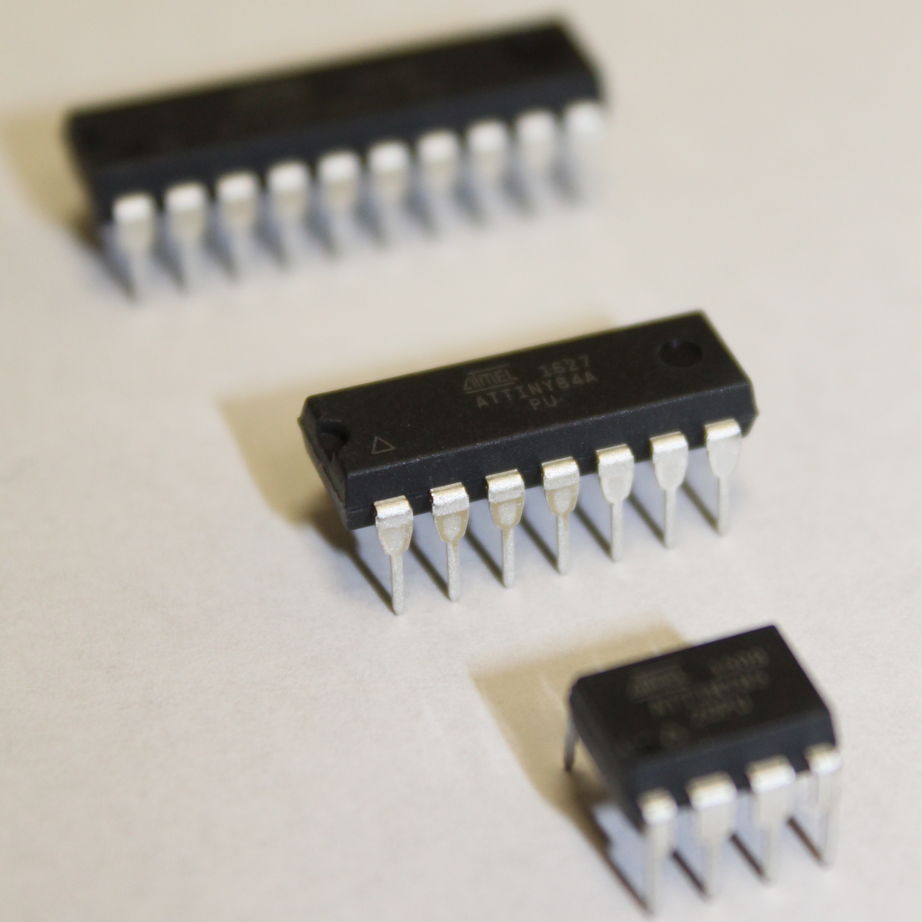
In this module, we put the hardware down for a bit and delve into a different topic - programming microcontrollers. Enter AVR microcontrollers made my Microchip Technology, formerly ATMEL. We will focus on two families of AVR microcontrollers: tinyAVR and megaAVR. From the tinyAVR family we will use the ATtiny85 and from the megaAVR family we will use the ATMEGA328p. Each microcontroller is different in its own ways with various features.
We will not be explicitly programming these AVR microcontrollers in this module. Instead, this module aims to familiarize you with them as we replace the Arduino UNOs that we have been using to prototype with an ATtiny85 and an ATMEGA328p, so that in the PCB design modules you will have some background to design the BT RC Car Remote and Vehicle using these new modules. Normally in your own time, as we had done before you would prototype with the ATtiny85 and ATMEGA328p explicitly, but we had the problem of noise so you will not see any appreciable results.
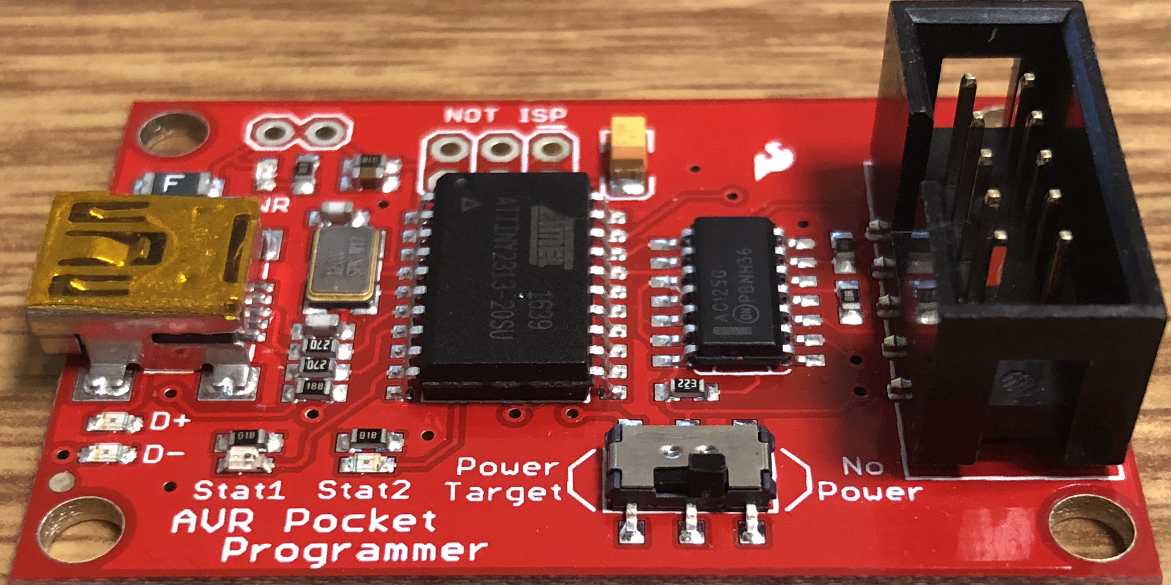
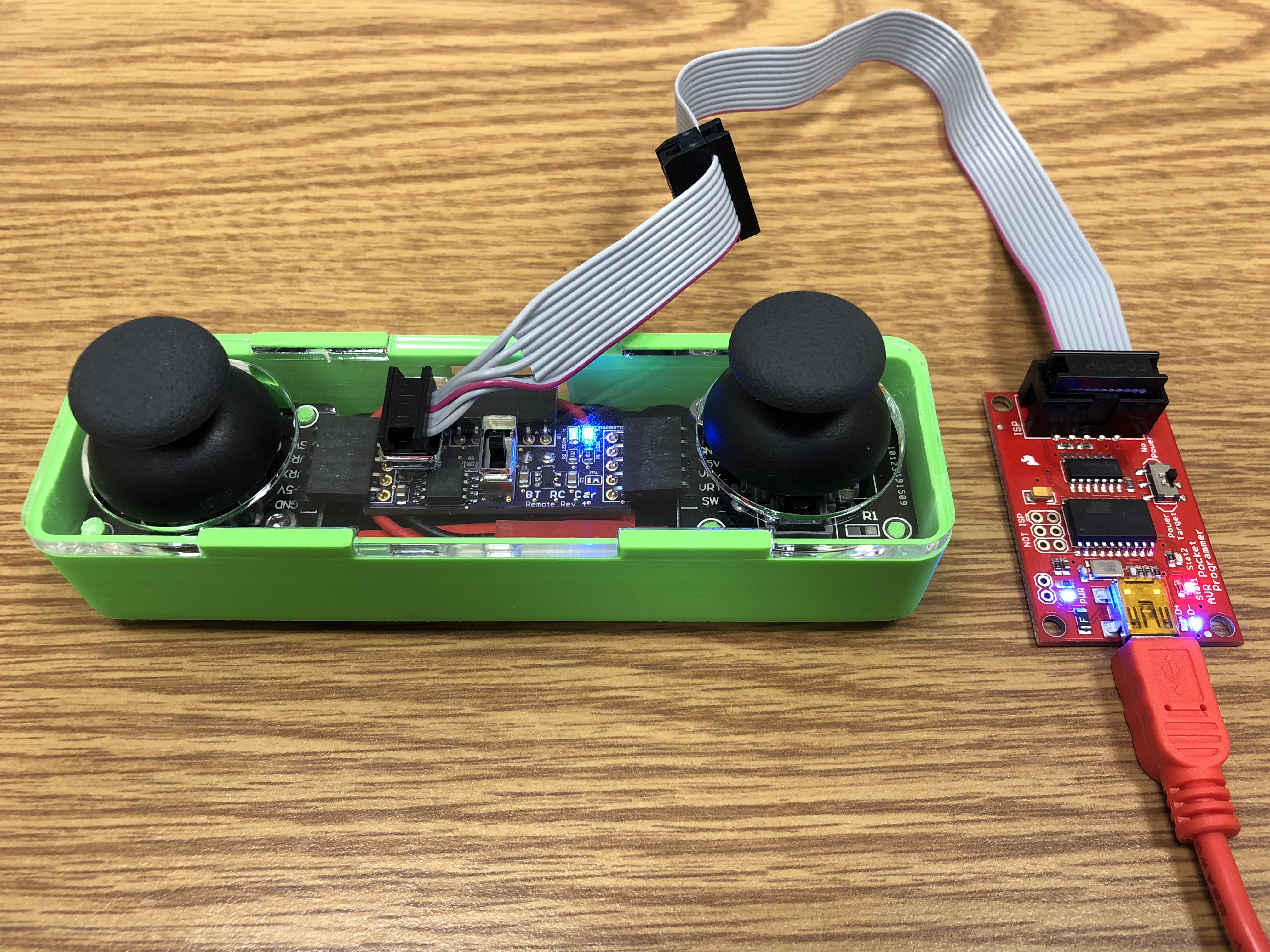
To learn about AVR microcontrollers in general we direct you to our AVR Microcontrollers tutorial. You will need to follow the sections for both ATtinys and ATMEGAs since we will be using both in this project. We will be using the Sparkfun Pocket AVR Programmer as our bootloading device, you may skip any mentions of Arduino as an ISP.
After reviewing the AVR microcontrollers tutorial, you should have the ATtinyCore bootloaders installed, be familiar with the board settings for both ATtinys and ATMEGAs. (For the ATMEGA328p, it is essentially the Arduino UNO, so not much to be aware of here). You should also have your Pocket AVR Programmer configured for your computer.
Next, we will introduce the ATtiny85 and ATMEGA328p explicitly and how we will be using it in this project!
We will now cover the ATtiny85 and ATMEGA328p in detail as it pertains to the BT RC Car. This includes how we will convert the prototyping we have done up to this point on the Arduino UNO. That is, how we will use the ATtiny85 to replace the Arduino UNO for the remote and how we will use the ATMEGA328p to replace the Arduino UNO for the vehicle.
We will be using the ATtiny85 in our BT RC Car remote. It is extremely small and has just the right number of pins to be a perfect fit as our remote. We used the Arduino UNO to do our prototyping, and now we need to port our pin mapping and code to the ATtiny85. There are some changes that need to be made, but it is certainly possible!
Now we will cover the ATtinyX5 series in general and then how we will use the ATtiny85 explicitly in the BT RC Car. To learn about the ATTinyX5, we direct you to our ATtinyX5 Microcontroller tutorial. Since we will be using the Sparkfun Pocket AVR Programmer, you need only pay attention to the sections pertaining to the Pocket AVR Programmer explicitly to bootload and program the ATtiny85. We cover the ATtinyX5 through-hole package in the general tutorial, but the pinout is exactly the same, as well as any behavior, so they are identical to each other in every way except one is a surface mount chip and the other is a through-hole chip.
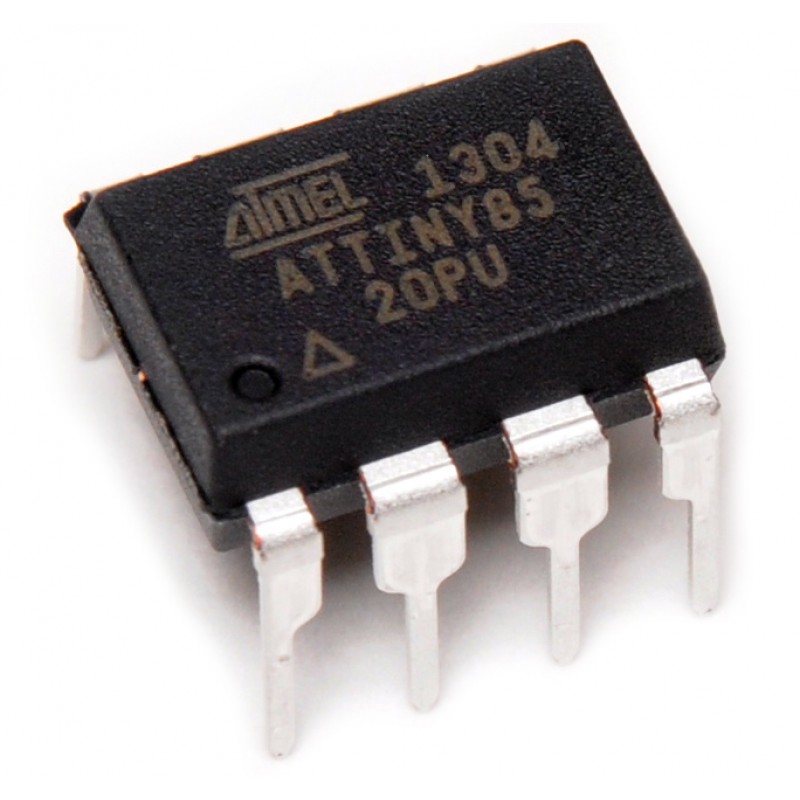
Here we show a reference of the ATtiny85 pinout:
This pinout describes the physical and logical layout of the ATtiny85. The physical layout are the physical pins - pins one through eight in a counter-clockwise fashion. The logical layout of the ATtiny85 are the numerous labels tied to each physical pin.
We have the ATtiny85 device in our EAGLE libraries and it is represented as follows:
Observe the similarities and differences. The numbers represent the physical layout of the ATtiny85. However, the order of these numbers do not match the physical layout of the ATtiny85. The reason is because they are organized logically. On the left, the power connections are shown (i.e. VCC and GND). On the right, the GPIO (general purpose input and output) pins are labeled and ordered by port (e.g. PB = port B).
Each of the GPIO pins have one or more functions. The pins that you can program using the ATtinyCore in the Arduino IDE are labeled on the far right inside the parentheses (e.g. D# for a digital input or output pin, A# for an analog input pin, PWM# for a digital PWM or analog output pin). You would use these pins like you would in any typical Arduino sketch.
Back to the remote, so we need to think about what pins we used for the remote. From the module 05 Challenge: Prototyping BT RC Car Functionality, we have a circuit that should be similar to the following:
Observe we need power, two analog pins, and a means by which we can communicate to the bluetooth HM-10 over serial. On the Arduino UNO, we have a hardware UART with a dedicated TX and RX pin. On the ATtiny85, we are not so fortunate. But, there is a solution and we were prototyping with it the whole time. That is, we were using a SoftwareSerial library on the Arduino UNO. Technically on the Arduino UNO we could have used the hardware UART the entire time (and probably would have had increased speed and performance), but we were using SoftwareSerial and the ATtiny microcontrollers are capable of using this library.
Technically we could use any pin for the SoftwareSerial on the ATtiny85, but we need to make sure, of the five GPIO pins, we still have two analog pins in addition to the two pins we will need for TX and RX with SoftwareSerial.
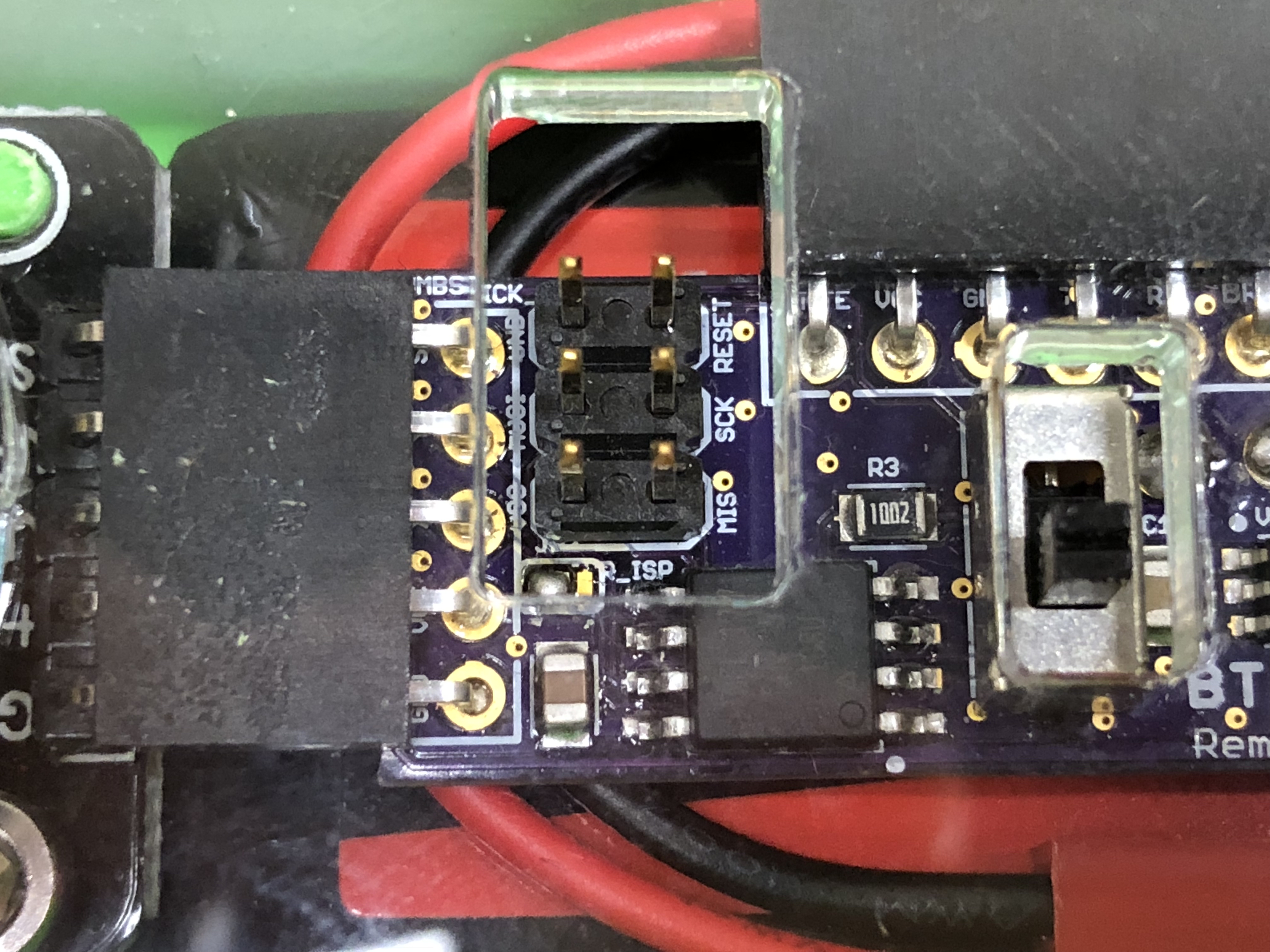
As you read in the AVR Microcontroller and ATtinyX5 Microcontroller tutorial we will need to bootload the ATtiny85. This requires the AVR ISP programming header to be present and we need to make these appropriate connections on our ATtiny85 as well. Since we only use this once and independent of any of the BT RC Car functions, we label them implicitly, in parenthesis, if they are doubling up with another pin necessary for the BT RC Car Remote. The pins we have chosen and use in the PCB provided are the following:
| ATtinyX5 (physical pin) |
Connected Device(s) | Schematic Label |
|---|---|---|
| 1 | AVR ISP | RESET |
| 2 | THUMBSTICK | THUMBSTICK_R |
| 3 | THUMBSTICK | THUMBSTICK_L |
| 4 | ALL | GND |
| 5 | AVR ISP LED |
MOSI |
| 6 | Bluetooth AVR ISP |
TX (MISO) |
| 7 | Bluetooth AVR ISP |
RX (SCK) |
| 8 | ALL | 3.3V |
If this appears a bit confusing, it should hopefully become more clear when we design the PCB board for the remote. But this is giving you a preview of how we are mapping the Arduino UNO pins to the ATtiny85 for our remote to retain the same functionality.
So this is how we will use the ATtiny85 to replace the Arduino UNO. We are being extremely efficient in this way. The Arduino UNO, and even the ATMEGA328p microcontroller that the Arduino UNO is based off the ATMEGA328p, is a lot larger and more expensive, but the ATtiny85 is very small and we are using every pin on the ATtiny85. This is the efficiency.
Next, we discuss the ATMEGA328p explicitly and how it will be our microcontroller for the BT RC Car Vehicle!
We will be using the ATMEGA328p in our BT RC Car vehicle. It is the exact same microcontroller at the heart of the Arduino UNO. The difference here is that we will be using a surface mount package that is a lot smaller, versus the through hole package that rests on the Arduino UNO development board. We used the Arduino UNO to do our prototyping, and now we need to port our pin mapping and code to the ATMEGA328p. Luckily, we did not choose the pins we have for just any reason. We have used the exact same pins in prototyping the vehicle on the Arduino UNO as we will use in the BT RC Car Vehicle PCB. There is only one change we will make, and that is taking advantage of the hardware UART in the ATMEGA328p and use it to perform our serial bluetooth communication (instead of using SoftwareSerial as we have during the prototyping phase).
Now we will cover the ATMEGA328p in general and then how we will use the ATMEGA328p explicitly in the BT RC Vehicle. To learn about the ATMEGA328p, we direct you to our ATMEGA328p Microcontroller tutorial. Since we will be using the Sparkfun Pocket AVR Programmer, you need only pay attention to the sections pertaining to the Pocket AVR Programmer explicitly to bootload the ATMEGA328p. We will not, however, use the Pocket AVR Programmer to program the ATMEGA328p. Instead, we will be using the Sparkfun FTDI Basic Breakout. We cover the ATMEGA328p through-hole package in the general tutorial, but the package we will use on the BT RC Car is a bit different. The ATMEGA328p PDIP (plastic dual in-line package) package is a through hole package (in the general tutorial) that has 28 pins, however the package we will use is a surface mount device in the industry standard TQFP (thin quad-flat package) package which has 32 pins. The only difference is that we have four extra pins, two of which is an extra VCC and GND pin, the other two are not being used. So we effectively have the same number of GPIO pins and are the same in every respect that we will use it.
One of the beautiful advantages to this, is that we can literally program our BT RC Car Vehicle and the ATMEGA328p microcontroller package that we are using exactly like we would an Arduino UNO. For all intense and purposes we are creating a custom Arduino UNO that will behave exactly like the Arduino UNO development board - except that we do not have broken out GPIO pins.
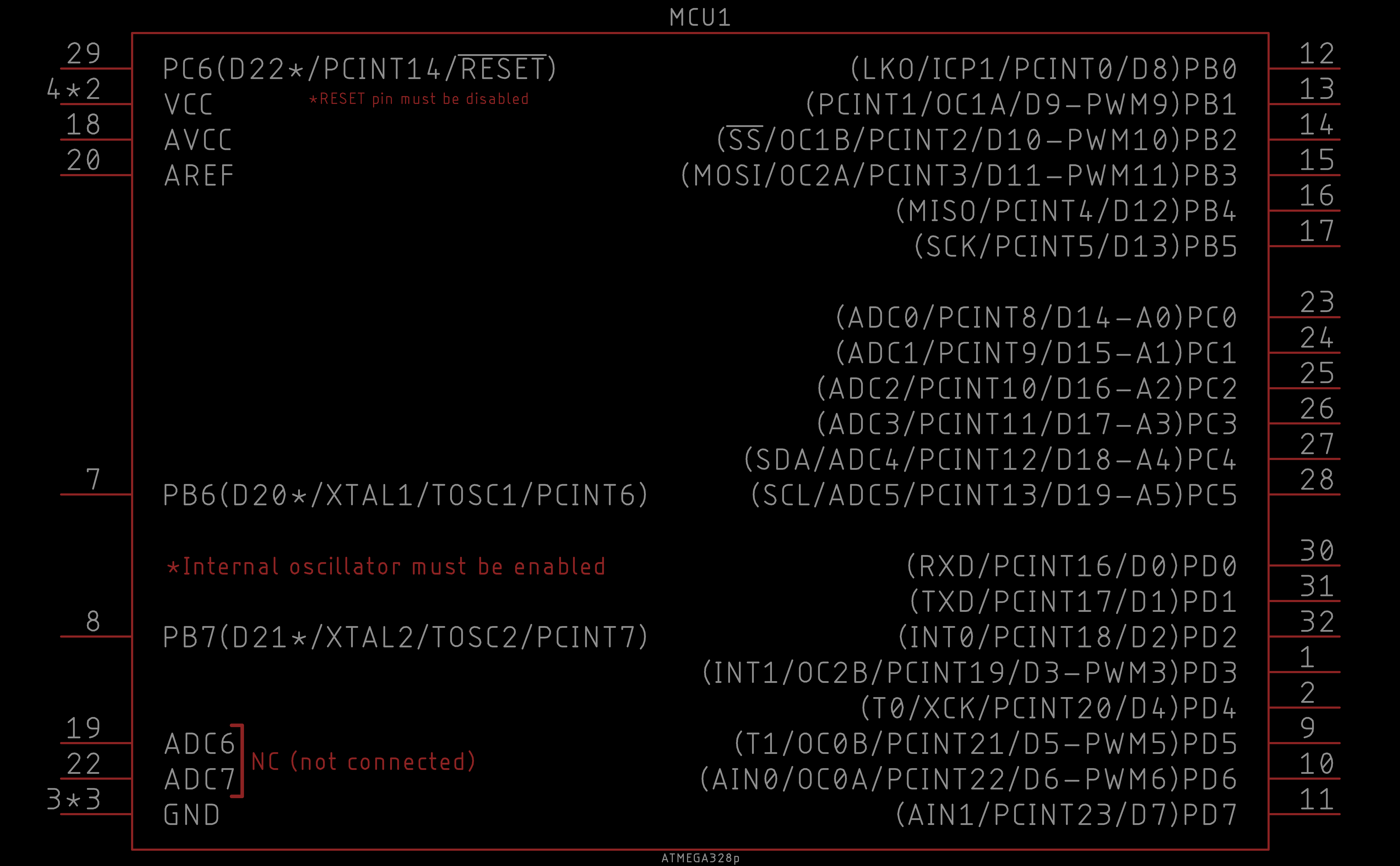
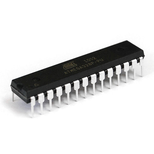
Here we show a reference of the ATMEGA328p TQFP pinout:
This pinout describes the physical and logical layout of the ATMEGA328p. The physical layout are the physical pins, namely pins one through 32 in a counter-clockwise fashion. The logical layout of the ATMEGA328p are the numerous labels tied to each physical pin.
We have the ATMEGA328p device in our EAGLE libraries and it is represented as follows:
Observe the similarities and differences. The numbers represent the physical layout of the ATtiny85. However, the order of these numbers do not match the physical layout of the ATMEGA328p. The reason is because they are organized logically. On the left, the power connections are shown (i.e. VCC and GND), the RESET pin, the crystal oscillator connections (i.e. pin 7 and 8), and some NC (not connected pins) (i.e. pin 19 and 22) that are literally not being used in any way shape or form. On the right, the GPIO (general purpose input and output) pins are labeled and ordered by port (i.e. port B, C, and D).
If you arguing that there are GPIO pins on the left-side, yes, you are technically correct. However, they are considered special, necessary, or completely useless. And for this reason we include them on the left.
Each of the GPIO pins have one or more functions. The pins that you can program using the Arduino UNO core in the Arduino IDE are labeled on the far right inside the parentheses (e.g. D# for a digital input or output pin, A# for an analog input pin, PWM# for a digital PWM or analog output pin). You would use these pins like you would in any typical Arduino sketch.
Back to the vehicle, so we need to think about what pins we used for the remote. From the module 05 Challenge: Prototyping BT RC Car Functionality, we have a circuit that should be similar to the following:
Observe we need power, one pin for the servo (does not necessarily need to be a PWM pin, but Arduino recommends pin 9 and 10 for servos), two PWM pins for the PHASE and ENABLE to control the H-bridge, and a means by which we can communicate to the bluetooth HM-10 over serial. On the Arduino UNO and thus ATMEGA328p, we have a hardware UART with a dedicated TX and RX pin. Although when we were prototyping we used the SoftwareSerial library to perform our bluetooth communication, we will take advantage of the hardware UART when it comes to the BT RC Car Vehicle.
As mentioned earlier, since the Arduino UNO and ATMEGA328p are effectively the same thing. We do not have to make any major pin changes except that when we design the PCB board, we will use the dedicated hardware UART TX and RX pins.
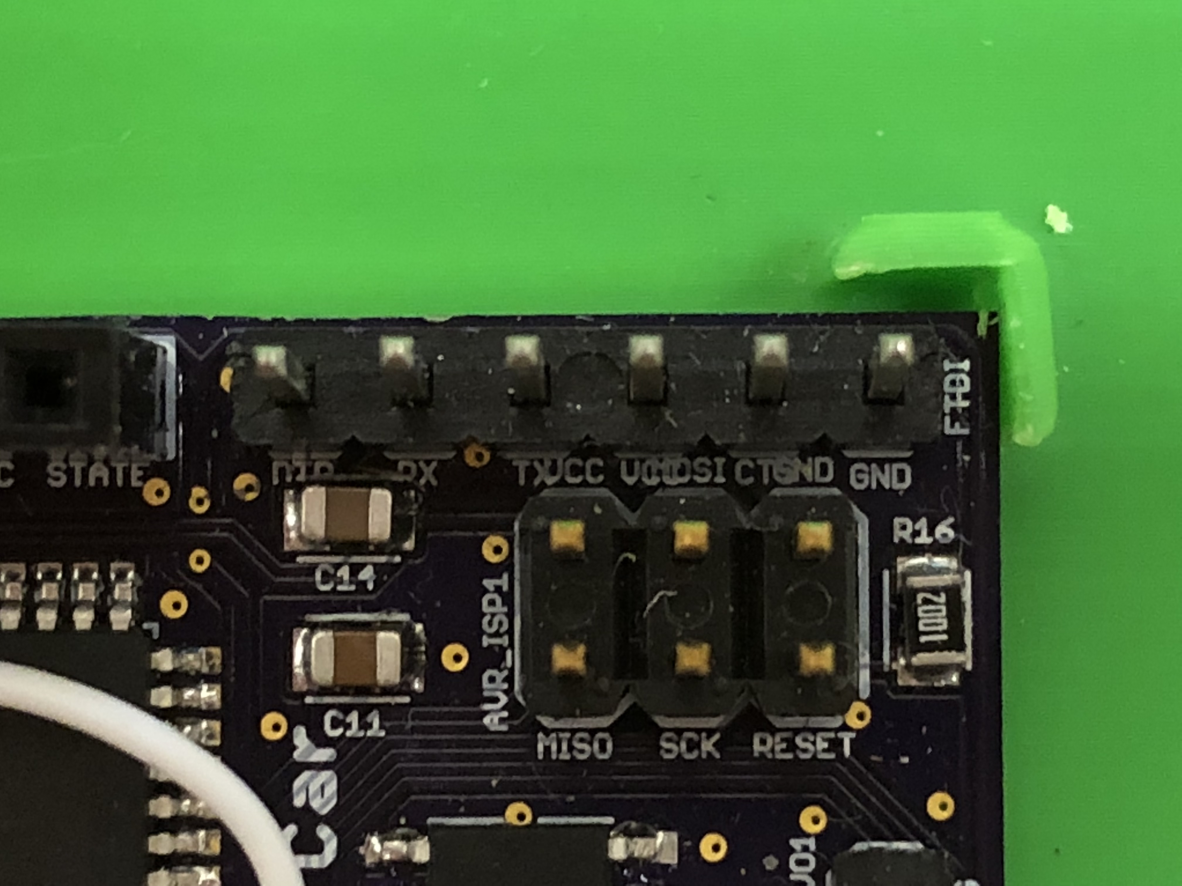
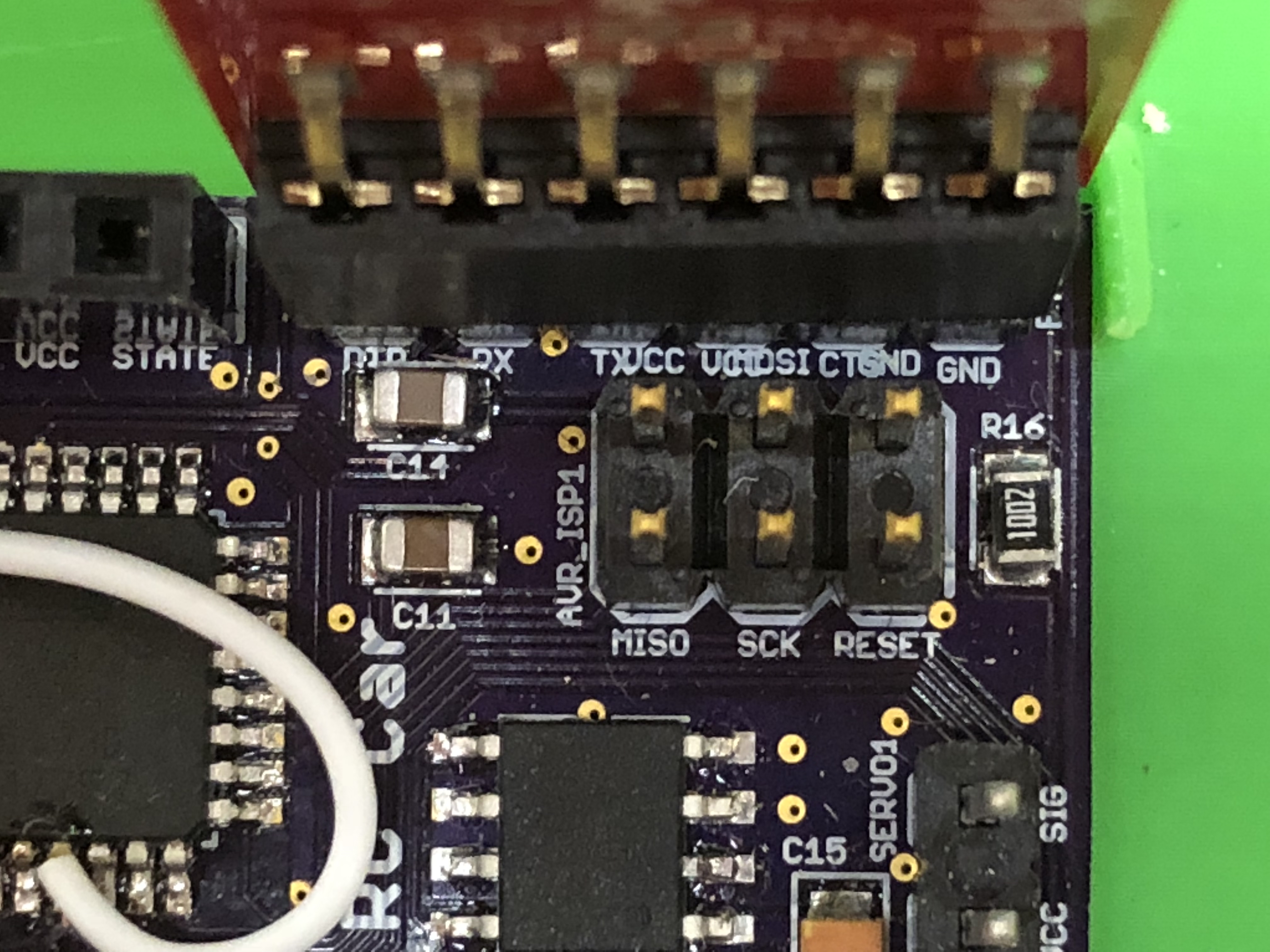
As you read in the AVR Microcontroller and ATMEGA328p Microcontroller tutorial we will need to bootload the ATMEGA328p and use a serial programmer to program the ATMEGA328p. This requires the AVR ISP programming header and the serial programmer header (we call it the FTDI header on the schematic) to be present and we need to make these appropriate connections on our ATMEGA328p as well. Unlike the case for the ATtiny85, we have no overlapping or doubling up of pin functionality. However, we still outline the pins we have chosen and use in the PCB provided are the following:
| ATMEGA328p (physical pin) |
Connected Device(s) | Schematic Label |
|---|---|---|
| 3, 5, 21 | ALL | GND |
| 4, 6, 18 | ALL | 5V |
| 7, 8 | Crystal Oscillator | XTAL1 |
| 9 | H-Bridge | PHASE |
| 10 | H-Bridge | ENABLE |
| 13 | SERVO | SERVO |
| 15 | AVR ISP | MOSI |
| 16 | AVR ISP | MISO |
| 17 | AVR ISP | SCK |
| 29 | AVR ISP | RESET |
| 30 | Bluetooth Serial Programmer |
RX |
| 31 | Bluetooth Serial Programmer |
TX |
If this appears a bit confusing, it should hopefully become more clear when we design the PCB board for the vehicle. But this is giving you a preview of how we are mapping the Arduino UNO pins to the ATMEGA328p for our vehicle to retain the same functionality.
That concludes the ATtiny85 and ATMEGA328p for now. We will revist these again after we design and solder the PCBs where we will discuss bootloading and programming the remote (ATtiny85) and the vehicle (ATMEGA328p).
Next up, we dive into the PCB design of the remote and vehicle!
We now turn to PCB design to advance our breadboard prototype into a printed circuit board (PCB) prototype. We will design both the BT RC Car remote and vehicle. The PCB design software we will use is Autodesk EAGLE.
Futhermore, we will finally create a solution to the noise problem during the breadboard prototyping phase as we will see shortly! This module contains several videos where we will walk you through the design. We believe, although the solution is presented with minimal minds-on thinking, that it is the best way to learn EAGLE and the reason behind the design of the BT RC Car PCBs.
So we ask that you pay very close attention to the way we are designing the PCBs here so that you can take what you observe and learn here into practice for your own future projects! Feel free at any point to deviate and add your own spin on the design.
If you have never used EAGLE or need a refresher, we have an Introduction to EAGLE PCB Design tutorial that we encourage you to follow. This tutorial will also get you started downloading and installing EAGLE. Furthermore, this will get you equipped with the basics so that you can keep up with the pace of the EAGLE content in this project. In these modules, we proceed slowly, however we are not going to go over the basic tools of EAGLE and assume you have the EAGLE Libraries integrated into the EAGLE environment.
Now we proceed with the PCB designing phase! We will first do the remote as it is an easier board. After, we turn to the vehicle which has a few more considerations that have to be taken into account while designing.
Let us make fun!
The next few lessons we are focused on building the schematic of the BT RC Car remote. This should look and feel very familiar to the schematics you have already built up to this point, the only difference is that we are using the ATtiny85 instead of the Arduino UNO.
We start right off the bat getting into EAGLE and getting the ATtiny85 onto the schematic.
We add the thumbsticks to the schematic with the jumper to allow the user to select which thumbstick controls throttle and steering.
We add the bluetooth HM-10 module for our wireless communication and AVR ISP header to bootload and program the ATtiny85.
We are solely focused on the power supply we will use to take our 7.4V lipo battery and power the BT RC Car remote. If you have never had to design with power in mind, pay close attention as referencing the datasheet is an important part of the design process.
We are completed with the schematic, now we switch over to the design of the board.
We start by shaping the board into a much smaller footprint. Then we do a rough placement of the main components in the remote design. Since the remote is somewhat symmetrical, we do what we can to keep the symmetry using EAGLE's grid to our advantage.
With everything placed on the board, we proceed with routing. This can be an extremely tedious process full of iterations and do-overs. Only when you start routing do you find some better alternatives for part placements to make routing easier for you.
Complete the routing of the board. At the end of this, we essentially have a completed board.
Generating a 3D model of our PCB board in Fusion360. Then showing some small changes you may want to make to any PCB board before shipping it out.
You may NOT be able to generate the 3D models because Autodesk has NOT set up sharing and thus all the 3D models are tied to my personal account. Sorry for the inconvenience.
At this point we are done with the BT RC Car remote. Next we do the same thing, but for the vehicle!
The next few lessons we are focused on building the schematic of the BT RC Car vehicle. This should look and feel very familiar to the schematics you have already built up to this point, the only difference is that we are using the ATMEGA328p and have to include the AVR ISP and the serial programmer. Both of which are already integrated onto the Arduino UNO, so we do not really think about them until we have to design it into our product.
We pick up the pace in the vehicle board design. It will feel similar to the remote in some ways, so we design a bit faster. It is also because we have a lot more to do - especially for the board design.
We start off adding the ATMEGA328p, bluetooth, AVR ISP, and Serial (FTDI) programmer.
We add the servo and the motor driver (i.e. H-bridge and motor) circuitry. Then we close with the power supplies. We have two power supplies here to isolate noise and for the different voltage demands of our various components.
As of Rev. 6 (of our PCB board), we added an LED + resistor. It is NOT in the video, but feel free to add an 0805 LED color of choice and the appropriately valued resistor on VBAT, or 5V.
We have completed the vehicle schematic, next we switch to the board editor and design our vehicle board.
Naturally, we start by shaping the board followed by a very rough placement of the components of the vehicle.
Next, we start routing. It gets annoying when we move or massage components around a bit, but that is just part of the design phase.
Continued routing of the board while displacing components around to making the routing come together nicely.
Complete the routing of the board. Here we focus on the power planes ground (GND) and noisy ground (NGND) and make sure we have clean and isolated power signals.
Add text and logos to the top and bottom of the board. Then port to Fusion360 so we can see the 3D model.
At this point we are done with the BT RC Car vehicle PCB!
We have completed the PCB design phase of the BT RC Car project! Next we will solder the PCB board replicas that we just designed.
In this module we will solder a replica of the PCB boards we just designed. We will employ the reflow soldering technique. Soldering with this technique works for only SMD (surface mount device) components.
Please take your time in this module as soldering is a relaxing and peaceful art. You should only solder when you are relaxed and stress free. Why? Because when you solder there should only be three things present: You, the board, and zen.
The point is, do not rush this and do it right the first time. We always tell students, the right way to solder is to do it right the first time. It is easy to make mistakes when soldering, but it is much harder to fix any soldering mistakes. Well... as you develop experience, fixing mistakes gets easier, but it very frustrating when you are not comfortable with the process.
We will be soldering remote and vehicle. We will start with the remote followed by the vehicle. When soldering boards that have both through-hole and surface mount devices, we start with the SMD components, then solder the through-hole after. There are a couple stages that we follow when soldering the surface mount components:
After which we solder all the through-hole components to complete the soldering phase.
Let us get started. First the remote, followed by the vehicle. Optionally, you could do them at the same time if you choose!
We apologize in advance for the poor choice for our hand model.
Here we start with the BT RC Car remote PCB.
First, we start with cleaning the board (optional step), and applying solder paste to the pads of the remote PCB.
Here we perform the actual pick and place of the surface mount components onto the board.
In the video, we place the LEDs in the wrong orientation, be warned!
Now we perform the actual reflow soldering of the board. We recommend you use an actual reflow station if available to you, but regardless the process is the same.
We apologize in advance for the noise of the heat gun used.
Careful to NOT burn yourself or heat/burn anything around you.
Here we solder the jumpers and through-hole components of the board.
This completes the soldering for the BT RC Car remote PCB! Next up, the same exact process for the BT RC Car vehicle PCB.
Do NOT power your device just yet!
Now we turn our attention to the soldering of the vehicle. The process is exactly the same as the remote except we have a few more components and a particular component that is relatively difficult to solder correctly.
As of Rev 6. We did not have the LED + resistor, so you will not see it in the videos. Be sure to address them as apropriate.
Again, we start with applying solder paste.
Careful to not put too much solder under the H-bridge component - fixing any mistake on this device will be quite difficult.
Next, we perform the pick and place.
Careful placing the H-bridge component to not smear the solder and for the pins to align.
Now we perform the reflow. If everything was done well, you should not have to worry about the H-bridge too much (even if we made several warnings). Generally the combination of solder mask and the reflow solder process will help your board come out well.
We apologize in advance for the noise of the heat gun used.
Careful to NOT burn yourself or heat/burn anything around you.
Finally, we solder the through-hole components.
This completes the soldering for the BT RC Car vehicle PCB!
Do NOT power your device just yet!
Next, we are going to do some simple tests for our boards to make sure they do not explode in your face when you turn them on. Perform these tests for both the remote and vehicle PCB.
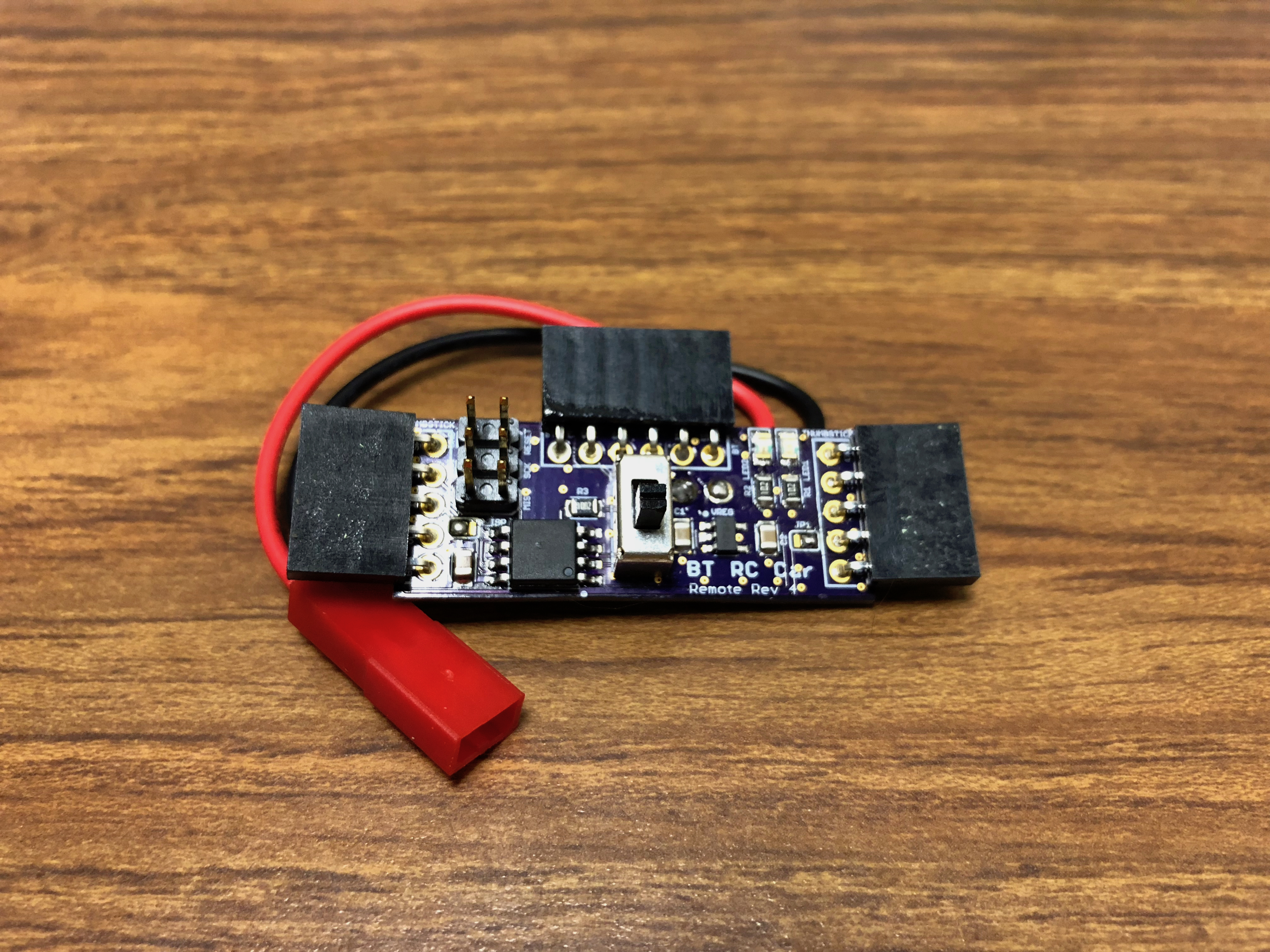
First, take a few minutes to visually inspect your board for any solder bridges. This is extremely important. If we shorted the battery at any place, something will get hot, smoke, or break. If we shorted any signals, then you will get garbage or static results that may result in the inability to program the device, read from sensors, or write to actuators.
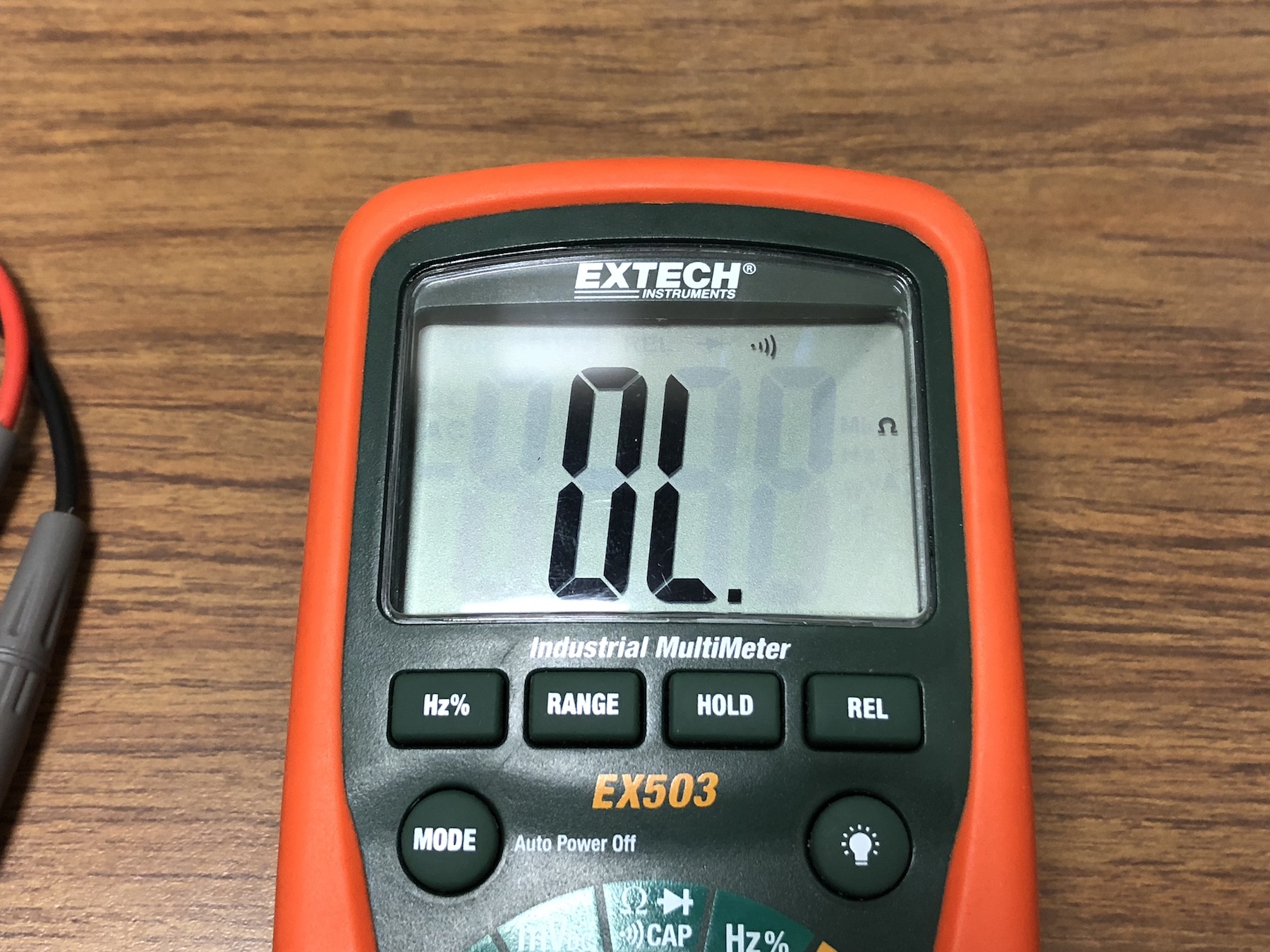
Next, retrieve a digital multimeters (DMM). Most decent DMMs will have a continuity check function available. Set the DMM to this continuity checking function. This continutity checking function will simply check the if the two points of contacts are connected electrically. So the first check we want to make sure that where the battery connects is NOT shorted. We can do this my touching the DMM leads to either terminal of the connector where the battery will connect.
The continuity check is not polarity dependent. But we encourage getting in the habit of touching the red lead to positive voltages and the black lead to negative voltages - or ground.
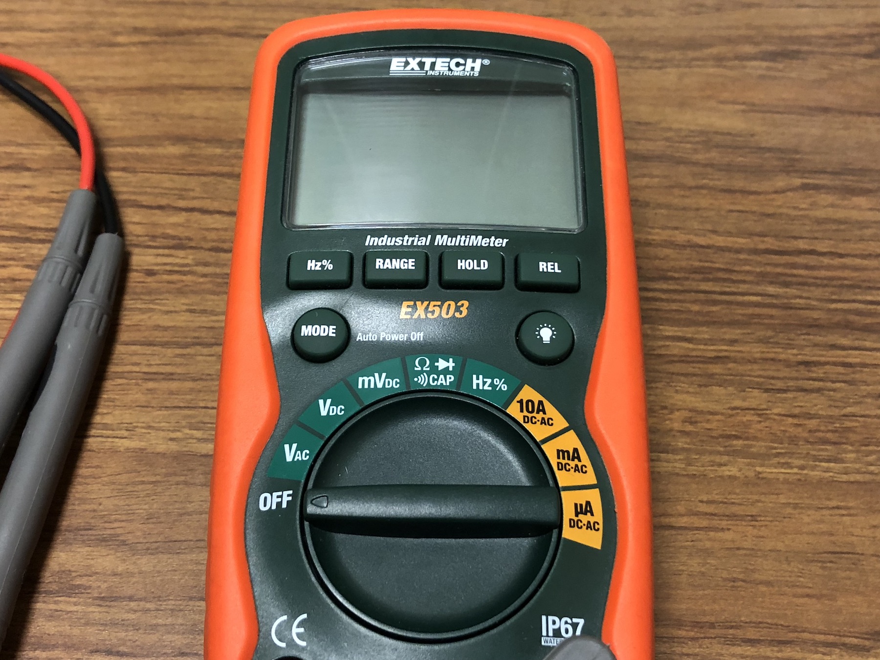
Most DMMs are very similar. If you have never used the continuity feature before, we illustrate how to use it on this model.
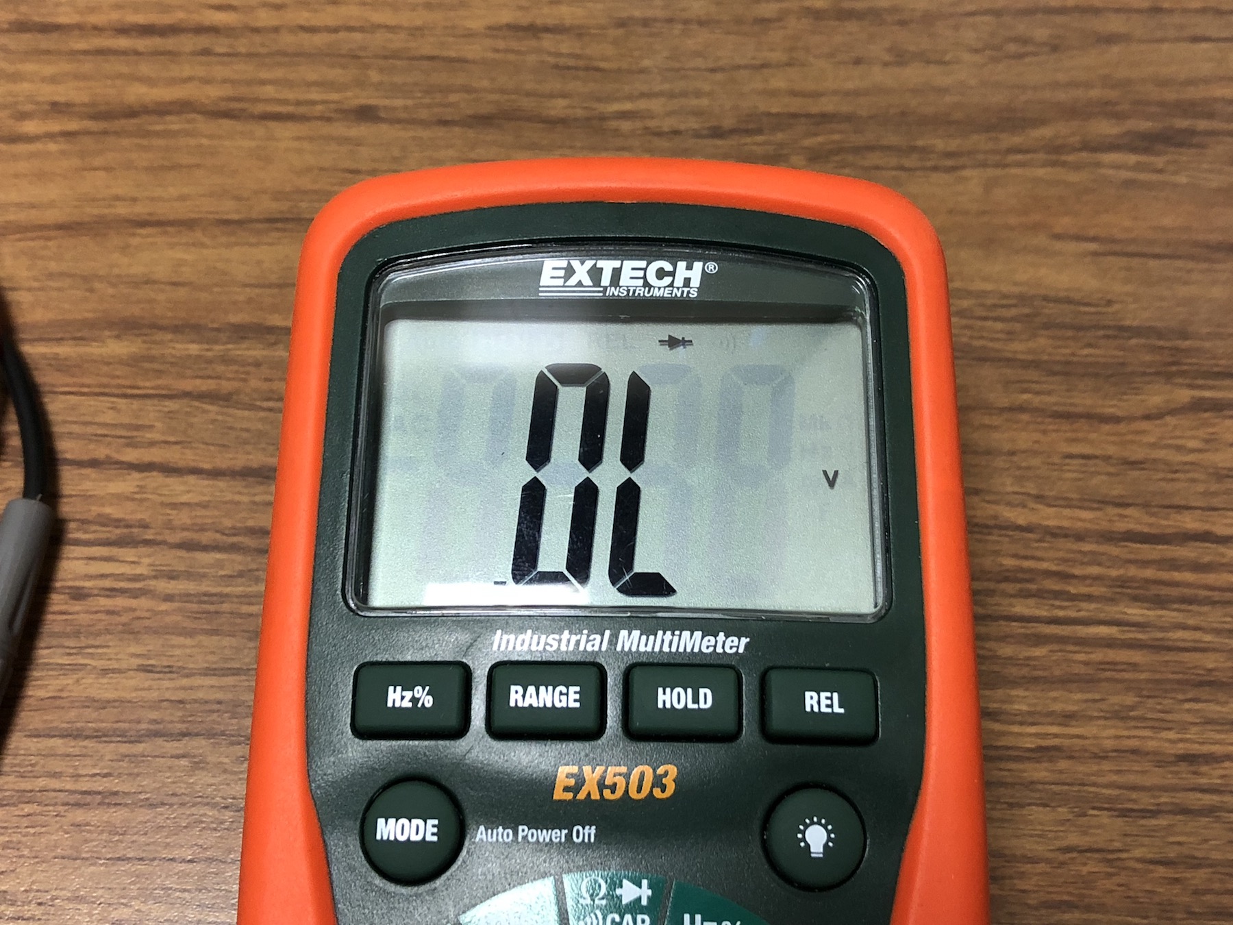
The symbol ![]() represents the continuity feature. On our DMM, the continuity feature is a mode on a dial position that is grouped with resistance mode and diode mode.
represents the continuity feature. On our DMM, the continuity feature is a mode on a dial position that is grouped with resistance mode and diode mode.
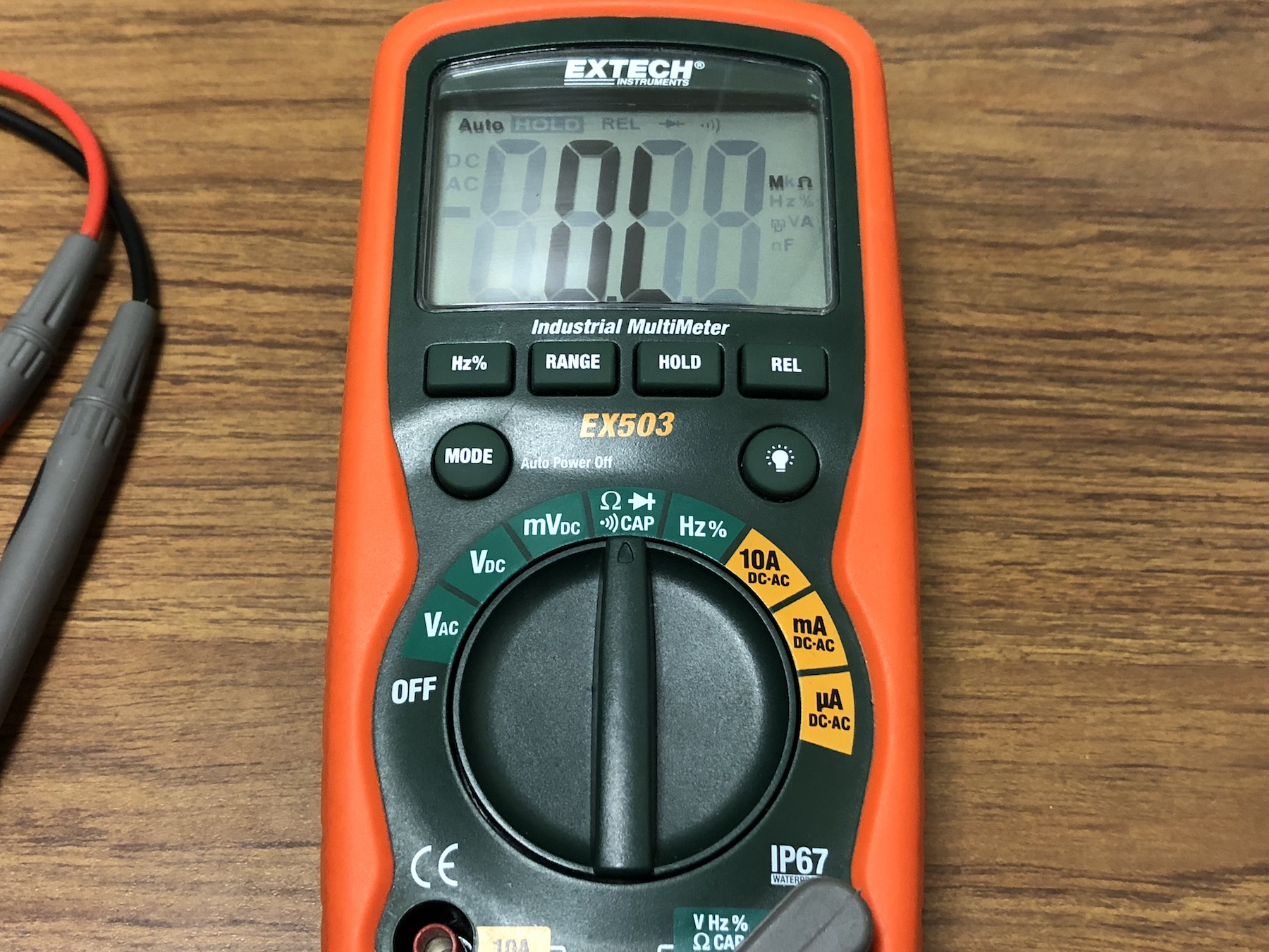
The mode button on the DMM cycles between the three modes. Select continuity mode.
At the top of the DMM display it shows which mode you are current on.
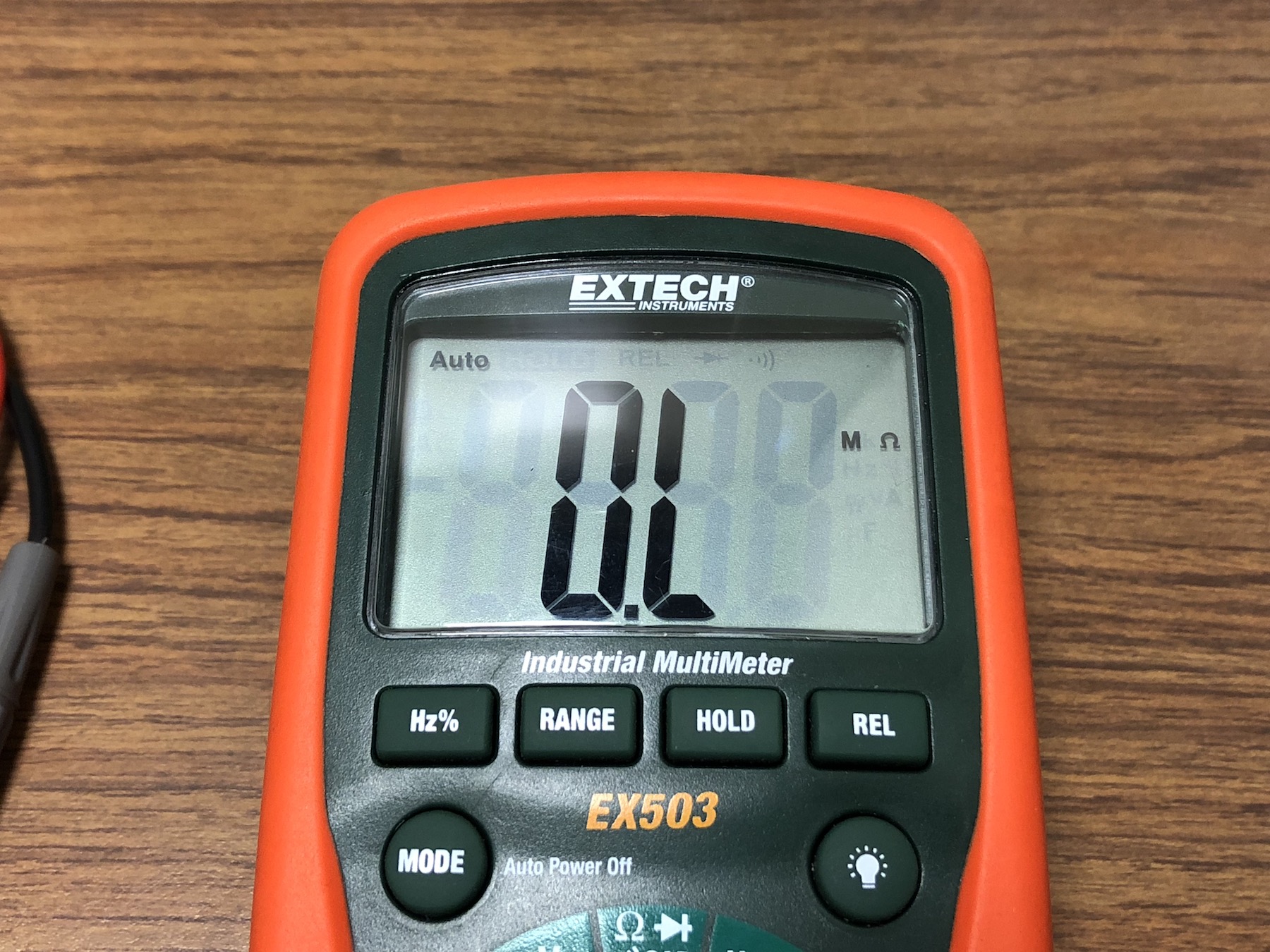
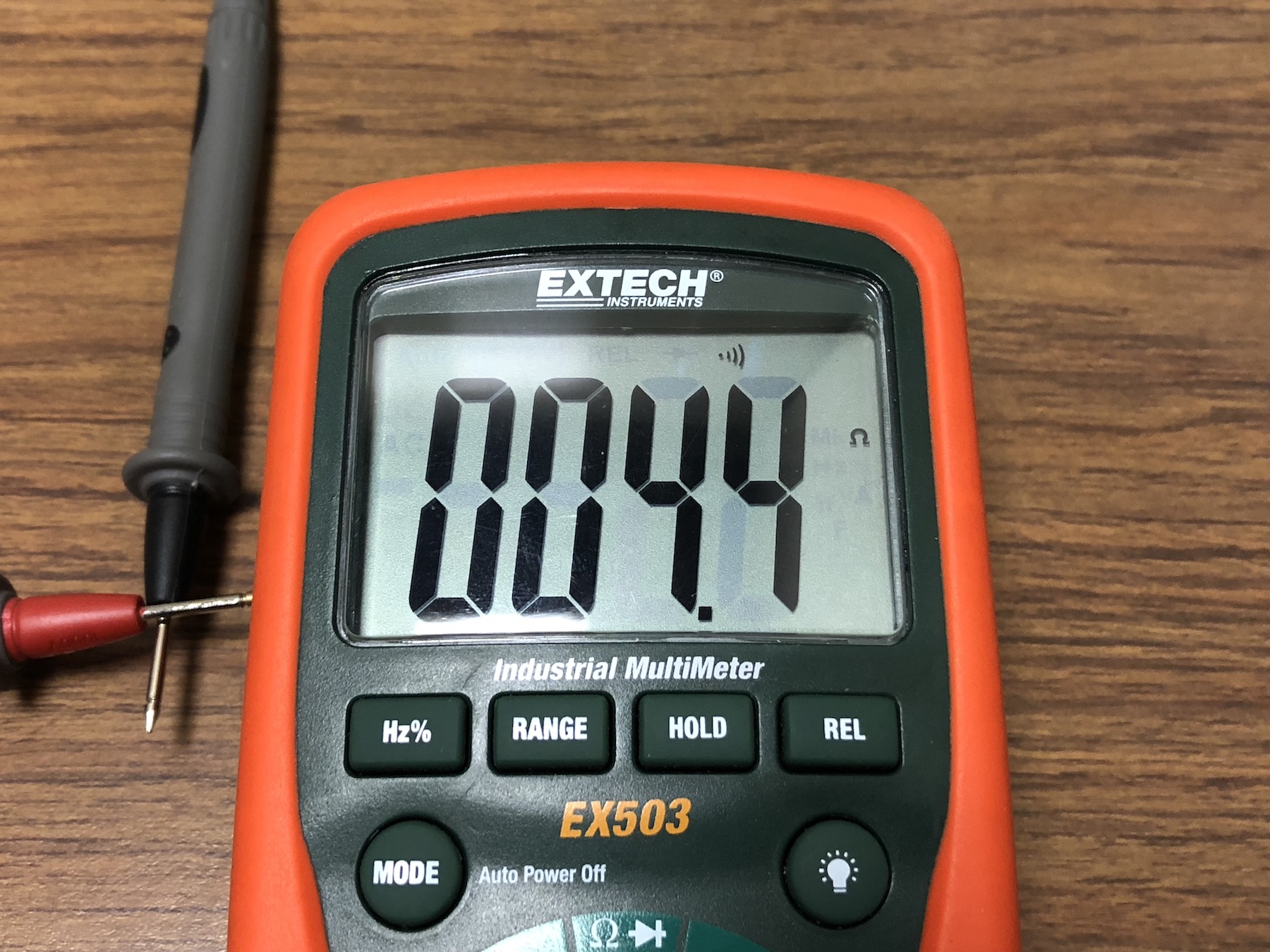
As a sanity check to check that the DMM is working properly, is set to the continuity mode, and that the leads are not broken (producing an open ciruit) anywhere, touch the leads of the DMM together.
If you hear a beep or observe that a resistance is displayed then you have a short and thus there is continuity. If there is no beep, or the resistance displayed is OL (overload), then you may be in the wrong mode or there is a problem with your DMM or the leads.
Now test continuity across the battery connector (should NOT beep). If you are NOT signaled that there are any shorts across the battery, you are so-far so-good, but we want to be absolutely certain. Take some time and check other parts of your circuit that you think may be shorted.
If you hear a beep or receive the signal that indicates that there is a short. Then you need to visually inspect your board again for any shorts. You may have to reflow or use a soldering iron and rosin to fix any devices that are shorted. It may also be good to test that certain components are connected too, in which a beep would be a positive test!
If you have a nice power supply available to you, many feature a current-limiting feature that is extremely useful for double-checking that your board does not have a short.
We have a short introduction to a Keysight E3631A DC Power Supply that supports this feature. If you have access to one or another power supply with similar features, we highly encourage taking this precaution and use it.
With this, you can set the current limit at 20mA, and the power supply output to 7.4V. Place the power supply leads across the appropriate positive and negative terminals of the PCB, respectively. You should see the power LED turn on. If the power LED does not turn on, flashes for a second and turns off, stays dim, or the power supply shows signs of a short. Disconnect the circuit and debug as appropriate.
Do NOT proceed any further until you are confident that you do not have any shorts. If any shorts exist, only smoke and fire exist beyond this point.
If you are not fortunate to have such a power supply, then at this stage, you have to take your chances and power your device. Or if you did, then it is time to power your device with the real thing. We recommend keeping close to the power switch or have the ability to remove the LiPo battery at a moments notice if you experience a short.
Shorting LiPo batteries are extremely dangerous.
If you see LEDs come on and no immediate shut-off, smoke, or popping sounds. You are probably good. We recommend lightly placing your fingers on each of the integrated circuit (IC) components (most notably the voltage regulators) to make sure they are not getting extremely hot. If so, immediately turn off the device and debug as appropriate.
This completes the soldering of the remote and vehicle PCBs. Be sure to add a small dab of glue on the wires to keep them from breaking on both PCBs. Your PCB should turn on with the LiPo battery and turn on the power LEDs. Nothing interesting will happen at this time, we have yet to program the PCBs. We will revisit the PCBs when we integrate them into the mechanical CADed parts, and then program them!
Next up, we move onto arguably the most anticipated part of the BT RC Car project - CADing and modeling the actual car and remote!
The goal of this module is to generate a 3D model of the BT RC Car vehicle and the remote. With these model files, you can 3D print and laser-cut the components to build your car and remote.
You will have the opportunity to:
Navigate to the following link to access the BT RC Car GitHub Repository. Clone or download the repository to your local machine. (Same process for obtaining the EAGLE Libraries shown in the Introduction to EAGLE PCB Design tutorial). Unzip the .zip if you downloaded the repository.
In the bt_rc_car folder, navigate to mcad > BTRC remote case. You need to 3D print the remote_case_botto.STL part in this folder.
In the bt_rc_car folder, navigate to mcad > BTRC vehicle chassis > 3D print STL parts of car. You need to 3D print all of the .STL parts in this folder.
3D print all the components as soon as you can in case some of the components do not print well.
You need to 3D print two copies of BackWheelV7.STL and FrontWheelV7.STL.
You must 3D print all components at the highest resolution (maximum infill and thinnest layers).
Watch and follow the following video where we walk you through the process of creating a 3D model in SolidWorks from a physical object through appropriate measurements.
You may 3D print this part now.
Watch and follow the following video to create a 3D model of your BT RC Car Vehicle chassis mainframe.
After completing the last video, navidate to the downloaded or cloned BT RC Car repository to bt_rc_car > mcad > BTRC vehicle chassis. Open the BTRC car frame documentation.PDF. This will have SolidWorks Drawing diagrams for the remaining parts. You need to create these parts following the same principle from the previous video.
Create parts A, B, C, and D.
You will need two copies of part A and part B for the SolidWorks Assembly.
You will need laser cut two copies of part A and part B for your complete chassis.
Do not laser cut your parts yet!
If you have not done so already, take the time to download and install Inkscape. The link to the Inkscape download page is here: https://inkscape.org/en/release/.
Next, watch and follow the following video where we demonstrate how to convert a SolidWorks object into a vector graphic. With this, we will be able to import a vector graphic into a 2D vector graphic software Inkscape. After which, we can use Inkscape to add some creativity and art to our PDFs that we will laser cut shortly.
Using the same principles as the previous video, personalize your remote cover. For example, you can add (a raster for) your name onto the cover. You can add other shapes and symbols. With some browsing around, you can find methods to engrave simple graphics from the web.
You may laser cut all BT RC Car vehicle chassis parts using ⅛" plywood. You may laser cut the BT RC Car remote cover part using ⅛" clear acrylic.
Finally, Watch and follow the following video where we demonstrate how we created the 3D model SolidWorks Assembly in the module 00 BT RC Car: System Overview.
This includes the CADing portion of the BT RC Car! Next, it is time to assemble everything together.
In this module, we assemble the remote and vehicle. We start with the remote as it is pretty straight forward, followed by the vehicle assembly which is rather difficult. When assembling the vehicle take your time to make sure it is done right and done well. From our experience and observations, the more attention to careful assembly and refining of the back wheels, the better the BT RC Car vehicle performed.
The remote is not terribly complicated in terms of assembly. But do be careful when assembling as everything is tightly fitted together.
You should have the following items from the Bill of Materials (BoM)
The M3 x 0.5mm thread 8mm long screws are optional, but recommended for structural integrity.
First we simply plug in the thumbsticks into the 5-pin right-angle (RA) female header pins.
Next, we insert the battery into the remote casing. The battery should fit snug into the remote. The battery leads can be facing either side on the top, or bottom. However, you should use strong tweezers to push the wires between the thumbstick peg so that it fits snug. Route the balancer connectors (i.e. the white JST connectors) around the pegs.
Connect the LiPo battery connector to the remote connector. Then fit the remote PCB into the remote casing. The thumbstick holes should fit snug around the pegs of the remote casing. Then screw in the screws.
If the thumbstick holes do not fit well around the pegs, do your best to get them to fit. It is OK if a couple of the pegs break, this is why we have the screws.
Do NOT screw in the screws too tight or you will destroy the 3D printed material.
Finally, simply place your remote cover over the remote casing, and plug in the bluetooth!
We purposely have the remote cover NOT glued to the remote casing. This is so you can remove the LiPo battery to recharge or replace, or fix any problems with the remote in the future.
You can go ahead and turn on your remote. It is not doing anything yet, however the power LED should turn on the same as in the soldering module testing phase.
And that is all there is to it for the remote! We will return to programming the remote in the Integration module. Next up, vehicle assembly!
Now we demonstrate the vehicle chassis assembly through the following video. Again, take your time on this part to do it correctly as it is much more difficult than the remote. Pay attention to detail as this is essential to produce a high-quality vehicle that will run fast and handle well.
After each instance of applying glue, let the pieces sit for about 10-15 minutes.
We demonstrate running the motor to strip some of the poorly printed 3D printed gears. At this stage of the assembly and after, we recommend running the DC motor with various voltages (up to a MAX of 7.4V) using a DC power supply to smooth out the gears. We recommend approximately 10 minutes or until the back-wheels move relatively smoothly when spinning the back-wheels with your hand (and feeling minimal resistance).
Do NOT solder the motor wires yet until the gears are smooth! (It may require holding off on installing the vehicle battery casing).
Before intalling the servo, use the Arduino UNO to write the servo to 90 dgrees. This ensures that the servo has 90 degrees in either direction (to maximize handling capabilities).
And this essentially completes the vehicle assembly. Be sure to run the motors to smooth out the gears.
To complete the vehicle assembly, solder the motor wires stemming from the PCB to the DC motor leads. We do not show any media for soldering the DC motor to the vehicle PCB motor wires - we hope this is straight forward. Do not worry about polarity, we will address the direction of motor actuation (or vehicle driving direction) in the Integration module.
We also recommend putting a small bit of glue where the motor tabs connect to the wires. We have found that these tabs break very easily.
Finally, onto the last module - actually putting this BT RC Car into action!
We are in the home stretch! We, essentially, have all the pieces laid out in front of us and have built a foundation for the code base. Now it is time to put it all together so we can finally drive this car around. During the course of this project, we had a lot of prep work and left a lot of loose ends untied. In this module, we bring everything around full circle!
However, we will run into a small problem that can make the realization of the final product, again, a bit farther away. That is, the ATtiny85 (i.e. the remote) does not have a hardware UART (remember?). So, when we were working with the Arduino, we could use Serial.print() commands to debug. So we need to be very careful with the code we upload, such that, we do not have any bugs that are hard to, well, debug since we do not have many resources to help us here. So please, proceed with caution. Fortunately, on the vehicle we have the ATMEGA328p which has a hardware UART - and thus, we do have debug statements!
Although, before we can even worry about not being able to debug anything - we need to bootload our remote and vehicle so we can get started programming them! So we will take you through some of the same or similar examples from earlier modules to test out the hardware as a sanity check. It is extremely important in engineering to test things independently first to make sure they are behaving appropriately. After each component is working as expected, then we can test the components all together adding them in one at a time. If things stop working along this path, you are aware that in the simple case it works, so you can always back track to a working state and progress slowly and carefully from there.
We will now progress testing the hardware on the remote one element at a time. Again, we do not have much to work with on the remote since we have no access to Serial debugging statements.
We encourage you to refamiliarize yourself with the AVR Microcontrollers and ATtinyX5 Microcontroller as they provide the general details of bootloading and programming the remote (i.e. ATtiny85). We will be using the Sparkfun Pocket AVR Programmer to both bootload and program the remote.
Remove the bluetooth if it is connected. Having the bluetooth connected messes up the upload process since they are sharing pins with the AVR ISP headers. It may result in bricking (i.e. destroying) your ATtiny85.
Rememeber, during the PCB Design: Remote & Vehicle module we did not connect the AVR ISP pins to power. So technically, we do not need to worry about the power target switch on the Pocket AVR Programmer. However, just to error on the side of caution and get you in the habit of being aware of it. Make sure the power target switch on the Pocket AVR Programmer is set to: No Power.
On the remote PCB, there should be an AVR ISP header as follows:
Note the small labels for the AVR ISP pins. With the Pocket AVR Programmer, insert the cable into the AVR ISP header as follows:
To remember the convention as to which direction the cable is to be inserted for future use, we use the following: The cable wires point towards VCC. Another convention is: MISO is pin 1 and is on the side of where the 2x3 cable header key resides
If you observed that there are two LEDs on, on our board, and one on yours, you are OK. Only one of your LEDs, the power LED, should be on. This photo was staged and taken after we already bootloaded and programmed the remote.
We are now ready to bootload the remote.
For both bootloading and programming the remote, do NOT have the bluetooth plugged into the remote. You risk destroying the ATtiny85.
Power on the remote if you have not already. Then, proceed to burn the bootloader.
If burning the bootloader fails, check that you are powering the remote and that you have the Pocket AVR Programmer cable mounted appropriately. If still no luck, debug the SPI connections between the AVR ISP header and the ATtiny85 to make sure none of them are shorted together, and that there is continuity between the appropriate signals.
Great! We are off to a good start.
Now it is time to program the ATtiny85. Fortunately, programming the ATtiny85 uses the same method as burning the bootloader.
We have intalled a debugging LED onto the remote. We were thinking ahead knowing the limited debugging capabilities of the remote without having a hardware UART.
So let us program the remote to simply blink this LED. If you recall from the PCB Design: Remote & Vehicle, the debugging LED pin connection is as follows:
| Device | Arduino IDE Programming Pin # |
|---|---|
| Debugging LED | 0 |
We will not display any media demonstrating this. It is pretty straight forward. If your LED is blinking at approximately the rate you set it at - you are good! If it is not, proceed to debug the circuit and check your code that you are using the appropriate pin or any other logic errors.
Next up, the thumbsticks. Again, we have no debugging statements to read from the thumbsticks and print them to the Serial Monitor. However, we just tested the onboard LED and we actually have this LED on a PWM pin - and for a good reason. The analog readings we get will be between 0 - 1023. Note that, this is different from when we prototyped on the Arduino UNO. Why? Because the analog reference on the Arduino UNO is 5V. Even though we were using 3.3V to the thumbsticks during the prototyping phase, the analog reference was still referencing to 5V! Since our remote is powered by a 3.3V regulator, the analog reference on the remote is also at 3.3V - hence why we will get readings between 0 - 1023.
With these readings, we can map 0 - 1023 to 0 - 255 and analogWrite() this mapping to our onboard LED. This is a convenient sanity check before we transmit the readings over bluetooth.
The pinout for the thumbsticks are as follows:
| Device | Arduino IDE Programming Pin # |
|---|---|
| Left thumbstick | A2 |
| Right thumbstick | A3 |
We test each of the thumbsticks, one at a time, writing the mapping to the LED. It is hard to see it because it is next to the bright power LED. But as long as you discern that the brightness is changing we are signaled that the thumbstick (and LED) are behaving.
Testing of the left thumbstick:
Your thumbstick may actuate on the opposite direction depending on how you soldered the jumper.
Observe the LED brightness changing - it is subtle.
Testing of the right thumbstick:
Your thumbstick may actuate on the opposite direction depending on how you soldered the jumper.
Observe the LED brightness changing - it is subtle.
That tests the thumbsticks. They are ready to be transmitted when we get to it.
This completes the testing on the remote. Not much, as the hardware and software is relatively simple. Next we move onto the vehicle which is a bit more involved.
Similar to th remote, We will be testing the hardware on the vehicle one element at a time. Luckily, we do have the Serial Monitor on our side here if needed.
We encourage you to refamiliarize yourself with the AVR Microcontrollers and ATMEGA328p Microcontroller as they provide the general details of bootloading and programming the vehicle (i.e. ATMEGA328p). We will be using the Sparkfun Pocket AVR Programmer to both bootload the vehicle - and this will happen just once. As for programming the vehicle we will utilize the Sparkfun FTDI Basic Breakout (3.3V) device (i.e. Serial Programmer).
Rememeber, during the PCB Design: Remote & Vehicle module we did not connect the AVR ISP pins to power. So technically, we do not need to worry about the power target switch on the Pocket AVR Programmer. However, just to error on the side of caution and get you in the habit of being aware of it. Make sure the power target switch on the Pocket AVR Programmer is set to: No Power.
On the vehicle PCB, there should be an AVR ISP header as follows:
Note the small labels for the AVR ISP pins. With the Pocket AVR Programmer, insert the cable into the AVR ISP header as follows:
To remember the convention as to which direction the cable is to be inserted for future use, we use the following: The cable wires point towards VCC. Another convention is: MISO is pin 1 and is on the side of where the 2x3 cable header key resides
We are now ready to bootload the vehicle (i.e. ATMEGA328p).
For bootloading the vehicle, do NOT have the bluetooth plugged into the vehicle.
Power on the vehicle if you have not already. Then, proceed to burn the bootloader.
If burning the bootloader fails, check that you are powering the vehicle and that you have the Pocket AVR Programmer cable mounted appropriately. If still no luck, debug the SPI connections between the AVR ISP header and the ATMEGA328p to make sure none of them are shorted together, and that there is continuity between the appropriate signals.
Great! We are off to a good start. Now we are ready to program the vehicle!
Now it is time to program the vehicle (i.e. ATMEGA328p). We will be programming the vehicle with the Sparkfun FTDI Basic Breakout - 3.3V (i.e. Serial Programmer).
We did not install a debugging LED onto the vehicle. Perhaps on a future iteration we will do this.
However, we will still describe the process for programming the vehicle here.
It is important to always remove the bluetooth if it is connected. Having the bluetooth connected messes up the upload process since it is connected to the same TX/RX pins as the Serial Programmer, so when the Serial Programmer tries to program the vehicle it sends signals to both the ATMEGA328p and the bluetooth HM-10. Both of these devices will "respond" to the attempt to be programmed and will confuse the Serial Programmer which will (usually) throw a syncing error on the Arduino IDE.
The location of the Serial Programmer headers is as follows:
There are some labels, however as you can see, they are being blocked by some other silkscreen and component footprints.
The Serial Programmer connects to the header as follows:
Be sure to power the vehicle, then uploading to the vehicle will be straight forward. It will be like literally programming a custom Arduino UNO.
Remember to also remove the bluetooth HM-10 when programming too!
Next, we will perform servo calibrations. After all we want the car to go as straight as possible without actuating the steering thumbstick. However, some servos with the horn attached, even written at 90 degrees will not be perfectly centered. Even with this calibration it might not be perfectly centered - however, we will do our best to center it. Other reasons for non-perfect straight movement depends on the wheels, some imperfections in the wheels, 3D printed parts, and laser cut pieces.
The other calibration we want to make is the servo handling, or turning, range. That is, how far will the wheels move in either direction when actuating the thumbstick. Ideally we would turn starting at the center of (ideally) 90 degrees, then turn left 90 degrees, and right 90 degrees, giving us the full 180 degree range of the servo. However, if you try this, the design of the vehicle does not allow the full 90 degrees. The 3D-printed servo bar that allows the wheels to turn will slip out before it reaches the full 90 degrees in each direction. Even if it could, we would not want this. Since our vehicle has a very simple design that does not utilize a differential to allow for better handling. So, if we turn too hard, the position of the wheels will start to reduce our ability to move the car forward and backward. (It is tough to describe, so feel free to experiment with this to see for yourself). With that said, this is designed to be a simple car. So, we want to restrict the range to allow an acceptable amount of handling. Regardless, it will still be a fun zippy BT RC Car.
The header for the servo is as follows:
The servo does have a polarity. There are three wires for the servo. Power, ground, and signal. Power (VCC) is red, ground (GND) is black, and signal (SIG) is orange or white. The PCB has labels for the servo header, so connect the servo appropriately.
The pinout for the servo is as follows:
| Device | Arduino Programming Pin # |
|---|---|
| Servo | 9 |
Now it is time to calibrate the servo. We will start by calibrating the center position.
We recommend to start by writing the servo at 90 degrees and see the alignment. Then proceed to adjust as appropriately until you are satisfied with the center-most position.
Next, we will calibrate the range of handling. With your newly defined center. We recommend sweeping the servo side-to-side evenly across the center. Calibrate the range with these couple things in mind:
Here is what our servo range calibration looks like:
This is probably about as much stress on the chassis we want to apply before we risk breaking the chassis or reducing the lifespan of the chassis.
Again, we are showing about the maximum distance, you are more than welcome to reduce the handling range, and even adjust this later as well after you start driving the BT RC Car around!
This sets the center and range calibration for the servo. Take note of these values, this range is what we will map the steering thumbstick to.
Finally, we will test the motor and H-bridge. We want to make sure that everything is working and that the motor rotates in both the forward and backward direction. This will also help us to determine what state phase needs to be written as for the appropriate forward and backward direction.
During our testing we do not want our vehicle to drive uncontrollably away from us, so make sure to prop-up the vehicle such that it cannot run away form us. We used the bluetooth modules (jokingly to remind you that you should not have them plugged in while we are programming the vehicle). But anything that allows at least the back-wheels to be raised will work.
Make sure nothing will rub against the gear that protrudes from the bottom of the vehicle when propping-up the vehicle.
The pinout for the H-Bridge is as follows:
| Device Physical Pin | Arduino Programming Pin # |
|---|---|
| H-Bridge enable |
6 |
| H-Bridge phase |
5 |
Next, you can write any program you want to test the vehicle. We are sweeping the motor up, from 0 - 255, then back down, from 255 - 0, in both the forward and backward direction.
If you hear a high-pitched whirring sound when writing very low PWM values - this is normal. It means that the motor is stalled and is not good for the motor in general. When the motor is stalled it pulls a lot of current, that may cause the servo to bug out (even though we were very careful to isolate the motor and servo from each other).
Take note of what state the H-Bridge phase is for both the forward and backward direction. We will map the throttle thumbstick to actuate the motor in the appropriate direction at the speed we desire.
This completes the testing on the vehicle. We are now ready to bridge the connection between the vehicle and remote via the bluetooth HM-10.
This is it. We tested all the hardware components except the bluetooth. And the reason is obviously because we need both devices to do this. This is where we have to take a leap of faith. Recall the ATtiny85 gives us no Serial Monitor feedback. However, the ATMEGA328p does! And, in our project we only need the remote to talk to the vehicle and tell the vehicle to turn and drive. So this one-way communication is easy to test. We have the remote transmit to the Vehicle. If we are receiving the data on the vehicle, print it to the Serial Monitor, and it looks good - we are in business! If we do not get any information or it is not correct. We need to review the code. Remember, unless you soldered something pooly, we guarantee the PCB having gone through several revisions will work properly.
For the bluetooth, we literally coded the appropriate behavior in the Bluetooth: HM-10 module for controlling the servo and motor on the Arduino UNOs. However, there are minor adjustments needed to map to the different hardware, but the logic is all the same.
With that, we expect you to test out the bluetooth module on your own from the remote to the vehicle. We will only tell you what the hard-wired pins in case you forgot from the PCB Design: Remote & Vehicle for bluetooth module to the remote and vehicle.
| Device Physical Pin | Arduino IDE Programming Pin # |
|---|---|
| Bluetooth TX | pin 1 using SoftwareSerial for BT comm |
| Bluetooth RX | pin 2 using SoftwareSerial for BT comm |
| Device Physical Pin | Arduino IDE Programming Pin # |
|---|---|
| Bluetooth TX | No pin using Serial for BT comm |
| Bluetooth RX | No pin using Serial for BT comm |
Again, before you jump all the way to transmitting thumbstick data to control the vehicle servo and motor. We highly recommend making a separate program to test just transmitting hard-coded data over bluetooth from the remote to the vehicle.
At this point, you should have confirmed that all components of the BT RC Car are working on both the remote and vehicle. The rest is in your hands. You have the foundation set and now you just need to complete the realization of the BT RC Car on the production hardware. We have taken you through the prototyping phase. Take what you have learned and apply it to create the BT RC Car!
Once you get your car driving, you have effectively completed the BT RC Car project!