Create your own custom Arduino UNO shield that programs ATtiny Microcontrollers!
Designed by:
Colin "MrSwirlyEyes" Keef
The ATTiny Programmer introduces you to system on a chip design. Many projects are prototyped using an Arduino or another development board. One generally utilizes only a subset of the total GPIO (General Purpose Input-Output) pins, and features of the microcontroller (MCU). Furthermore, the ATMEGA328P chip that the Arduino UNO runs on is very small compared to the overall size of the board. Thus, the Arduino UNO is quite large and cumbersome for projects that you want your Arduino permanently connected and dedicated to.
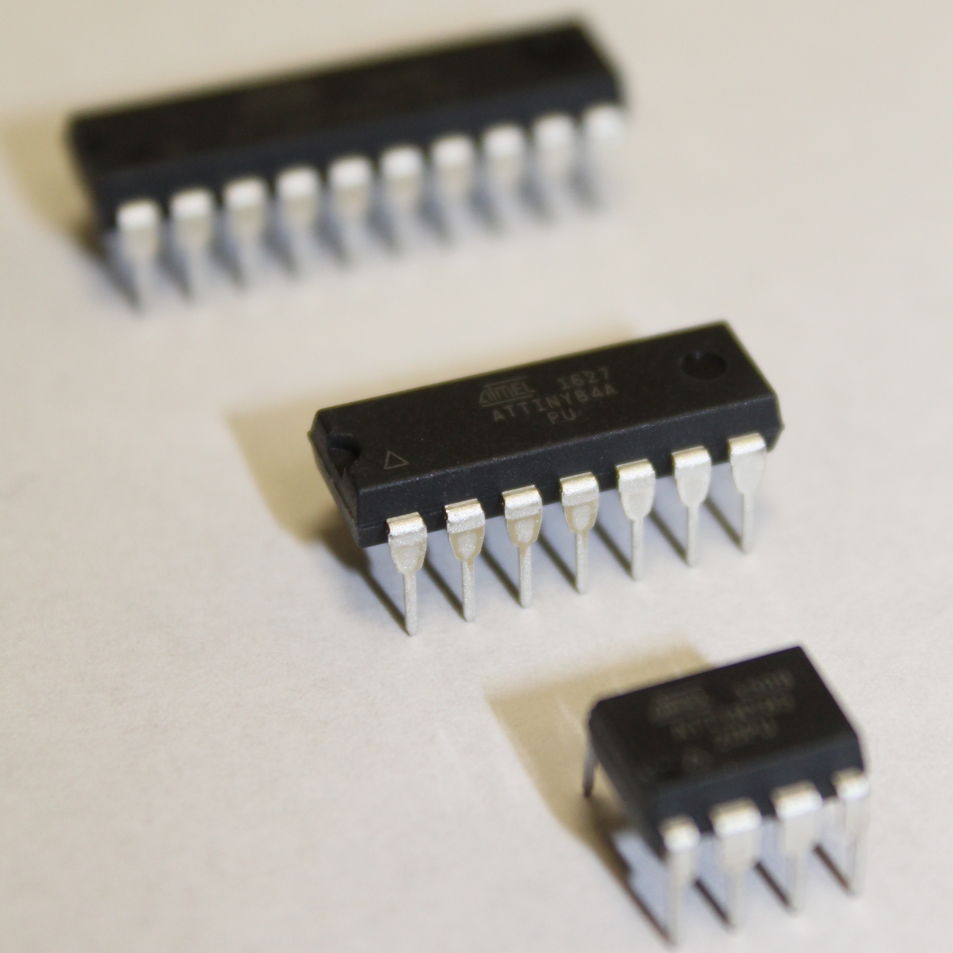
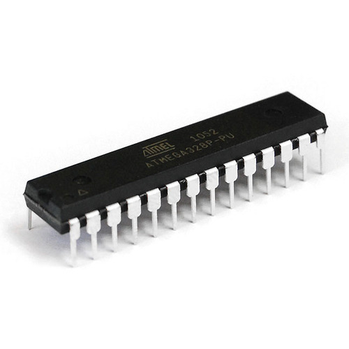
We now introduce ATtiny microcontrollers. These are of the ATMEL (now Microchip) tinyAVR microcontroller family, and are similar to the ATMEGA328P on the Arduino UNO. ATTiny variants come in various packages with a varying number of GPIO pins. We can use these ATTiny chips to replace development boards in projects where you use only a small subset of GPIO pins on the Arduino UNO. This will reduce your cost, area on your board or project, and will free your Arduino from a dedicated project so you may continue to use it for prototyping purposes.
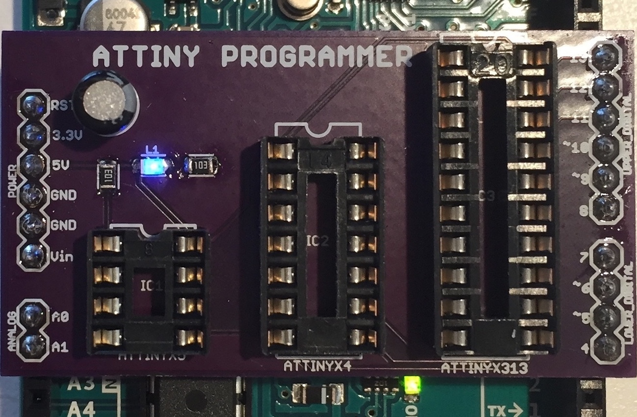
The ATTiny Programmer is an Arduino UNO shield. It is a PCB (Printed Circuit Board) that is attached to the Arduino UNO and can program three different ATtiny microchip through-hole variants: ATtinyX5 (8-pin), ATtinyX4 (14-pin), and ATtinyX313 (20-pin).
| DEVICE | VENDOR URL | QUANTITY | NOTES |
|---|---|---|---|
| Arduino UNO R3 | Digikey | 2 | May use other variants, but may need minor changes to code. |
| USB Cable (A Male to B Male) | Digikey | 2 | |
| ATtiny85 MCU IC 8BIT 8KB FLASH 8DIP | Digikey | 1 | May substitute for any other ATtinyX5 module. |
| ATtiny84 MCU IC 8BIT 8KB FLASH 8DIP | Digikey | 1 | May substitute for any other ATtinyX4 module. |
| ATTINY4313 8BIT 4KB FLASH 20DIP | Digikey | 1 | May substitute for any other ATtinyX313 module. |
| CONN IC DIP SOCKET 8POS TIN | Digikey | 1 | |
| CONN IC DIP SOCKET 14POS TIN | Digikey | 1 | |
| CONN IC DIP SOCKET 20POS TIN | Digikey | 1 | |
| LED BLUE CLEAR SMD 0805 | Digikey | 1 | |
| RES SMD 10K OHM 1% 1/8W 0805 | Digikey | 2 | |
| CAP ALUM 10UF 20% 50V RADIAL | Digikey | 1 | Aluminum Electrolytic Capacitor (polarized). Any similar value will work too. Any similar value will work too. Any similar value will work too. Any similar value will work too. Any similar value will work too. Any similar value will work too. Any similar value will work too. Any similar value will work too. Any similar value will work too. Any similar value will work too. Any similar value will work too. Any similar value will work too. Any similar value will work too. Any similar value will work too. Any similar value will work too. Any similar value will work too. Any similar value will work too. Any similar value will work too. Any similar value will work too. Any similar value will work too. Any similar value will work too. Any similar value will work too. Any similar value will work too. Any similar value will work too. Any similar value will work too. Any similar value will work too. Any similar value will work too. Any similar value will work too. Any similar value will work too. Any similar value will work too. Any similar value will work too. Any similar value will work too. Any similar value will work too. Any similar value will work too. Any similar value will work too. Any similar value will work too. Any similar value will work too. Any similar value will work too. Any similar value will work too. Any similar value will work too. Any similar value will work too. Any similar value will work too. Any similar value will work too. Any similar value will work too. Any similar value will work too. Any similar value will work too. Any similar value will work too. Any similar value will work too. Any similar value will work too. Any similar value will work too. Any similar value will work too. Any similar value will work too. Any similar value will work too. Any similar value will work too. Any similar value will work too. Any similar value will work too. Any similar value will work too. Any similar value will work too. Any similar value will work too. Any similar value will work too. Any similar value will work too. Any similar value will work too. Any similar value will work too. Any similar value will work too. Any similar value will work too. Any similar value will work too. Any similar value will work too. Any similar value will work too. Any similar value will work too. Any similar value will work too. Any similar value will work too. Any similar value will work too. Any similar value will work too. Any similar value will work too. Any similar value will work too. Any similar value will work too. Any similar value will work too. Any similar value will work too. Any similar value will work too. Any similar value will work too. Any similar value will work too. Any similar value will work too. Any similar value will work too. Any similar value will work too. Any similar value will work too. Any similar value will work too. Any similar value will work too. Any similar value will work too. Any similar value will work too. Any similar value will work too. Any similar value will work too. Any similar value will work too. Any similar value will work too. Any similar value will work too. Any similar value will work too. Any similar value will work too. Any similar value will work too. Any similar value will work too. Any similar value will work too. Any similar value will work too. Any similar value will work too. Any similar value will work too. Any similar value will work too. Any similar value will work too. Any similar value will work too. Any similar value will work too. Any similar value will work too. Any similar value will work too. Any similar value will work too. Any similar value will work too. Any similar value will work too. Any similar value will work too. Any similar value will work too. Any similar value will work too. Any similar value will work too. Any similar value will work too. Any similar value will work too. Any similar value will work too. Any similar value will work too. Any similar value will work too. Any similar value will work too. Any similar value will work too. Any similar value will work too. Any similar value will work too. Any similar value will work too. Any similar value will work too. Any similar value will work too. Any similar value will work too. Any similar value will work too. Any similar value will work too. Any similar value will work too. Any similar value will work too. Any similar value will work too. Any similar value will work too. Any similar value will work too. Any similar value will work too. Any similar value will work too. Any similar value will work too. Any similar value will work too. Any similar value will work too. Any similar value will work too. Any similar value will work too. Any similar value will work too. Any similar value will work too. Any similar value will work too. Any similar value will work too. Any similar value will work too. Any similar value will work too. Any similar value will work too. Any similar value will work too. Any similar value will work too. Any similar value will work too. Any similar value will work too. Any similar value will work too. Any similar value will work too. Any similar value will work too. Any similar value will work too. Any similar value will work too. Any similar value will work too. Any similar value will work too. Any similar value will work too. Any similar value will work too. Any similar value will work too. Any similar value will work too. Any similar value will work too. Any similar value will work too. Any similar value will work too. Any similar value will work too. Any similar value will work too. Any similar value will work too. Any similar value will work too. Any similar value will work too. |
| (1x02) CONN HEADER .100" SINGL STR 2POS | Digikey | 1 | |
| (1x04) CONN HEADER .100" SINGL STR 4POS | Digikey | 1 | |
| (1x06) CONN HEADER .100" SINGL STR 6POS | Digikey | 2 | |
| RES 10K OHM 1/4W 5% AXIAL | Digikey | 13 | Can substitute for appropriate sized resistor(s). |
| LED BLUE CLEAR T-1 3/4 T/H | Digikey | 13 | Can substitute for any desired color LED. |
| Breadboard (small) | Digikey | 2 | Used for prototyping. |
| Jumper Wire M/M 6 (20pcs) | Digikey | 2 | Used for prototyping. |
In this module, we introduce AVR microcontrollers made by Microchip Technology, formerly ATMEL. We will focus on one family of AVR microcontrollers: tinyAVR. From the tinyAVR family we will use the ATtinyX5, ATtinyX4, and ATtinyX313. Each microcontroller is different in its own ways with various features.
This module aims to familiarize you with each of the ATtinys to replace the Arduino UNO that we have been using to prototype.
To learn about AVR microcontrollers in general we direct you to our AVR Microcontrollers tutorial. You will need to follow the sections for ATtinys since we will be using an ATtiny variant in this project. We will be using the Arduino UNO as an ISP as our bootloading device, you may skip any mentions of the Sparkfun Pocket AVR Programmer.
After reviewing the AVR microcontrollers tutorial, you should have the ATtinyCore bootloaders installed, and be familiar with the board settings for ATtinys.
Next, we will introduce each of the ATtiny variants and how we will be using it in this project!
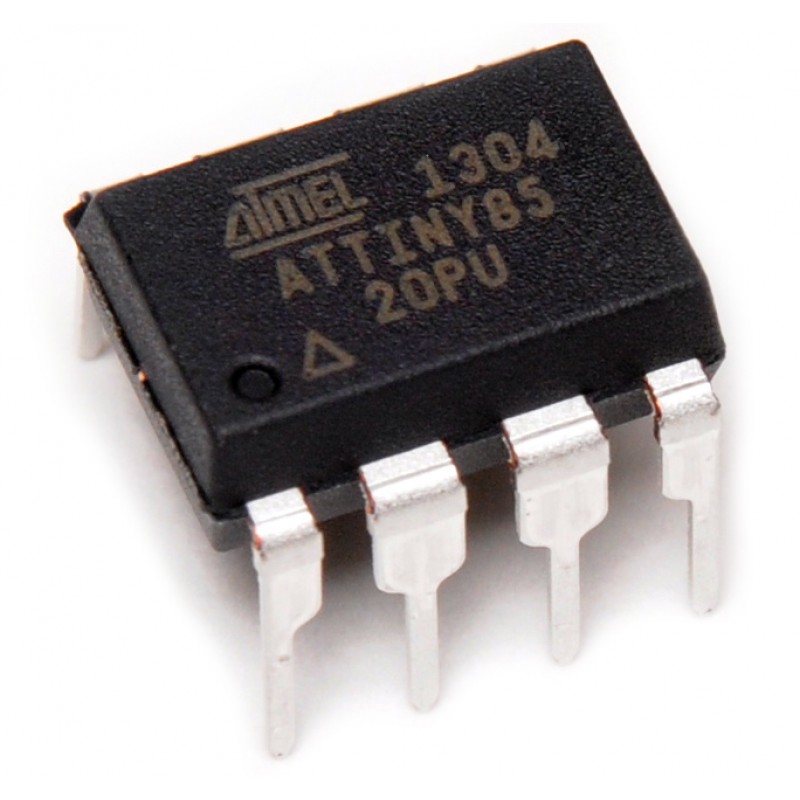
Now we will cover the ATtinyX5 series in general. The ATtiny Programmer's role is only to program the ATtinyX5. To learn about the ATTinyX5, we direct you to our ATtinyX5 Microcontroller tutorial. Since we will be using the Arduino UNO as an In-System Programmer, you need only pay attention to the sections pertaining to the Arduino as an ISP explicitly to bootload and program the ATtiny85.
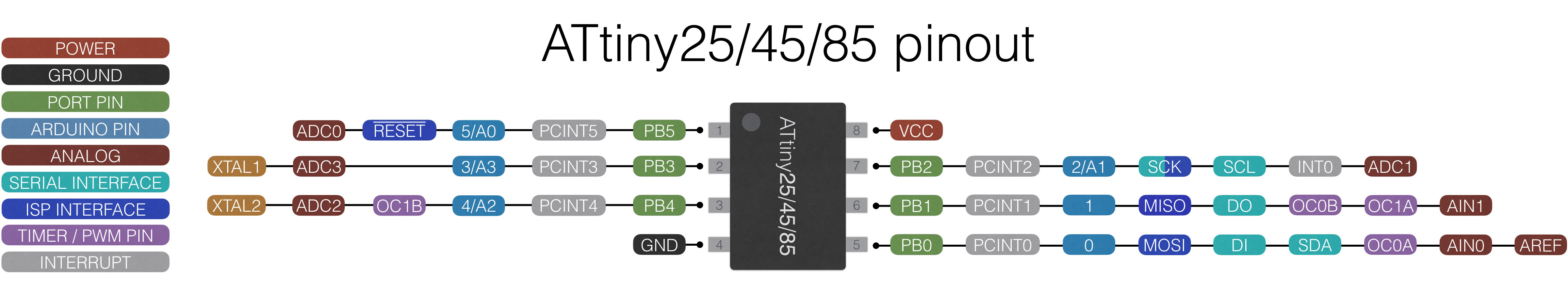
Here we show a reference of the ATtiny85 pinout:
This pinout describes the physical and logical layout of the ATtiny85. The physical layout are the physical pins - pins one through eight in a counter-clockwise fashion. The logical layout of the ATtiny85 are the numerous labels tied to each physical pin.
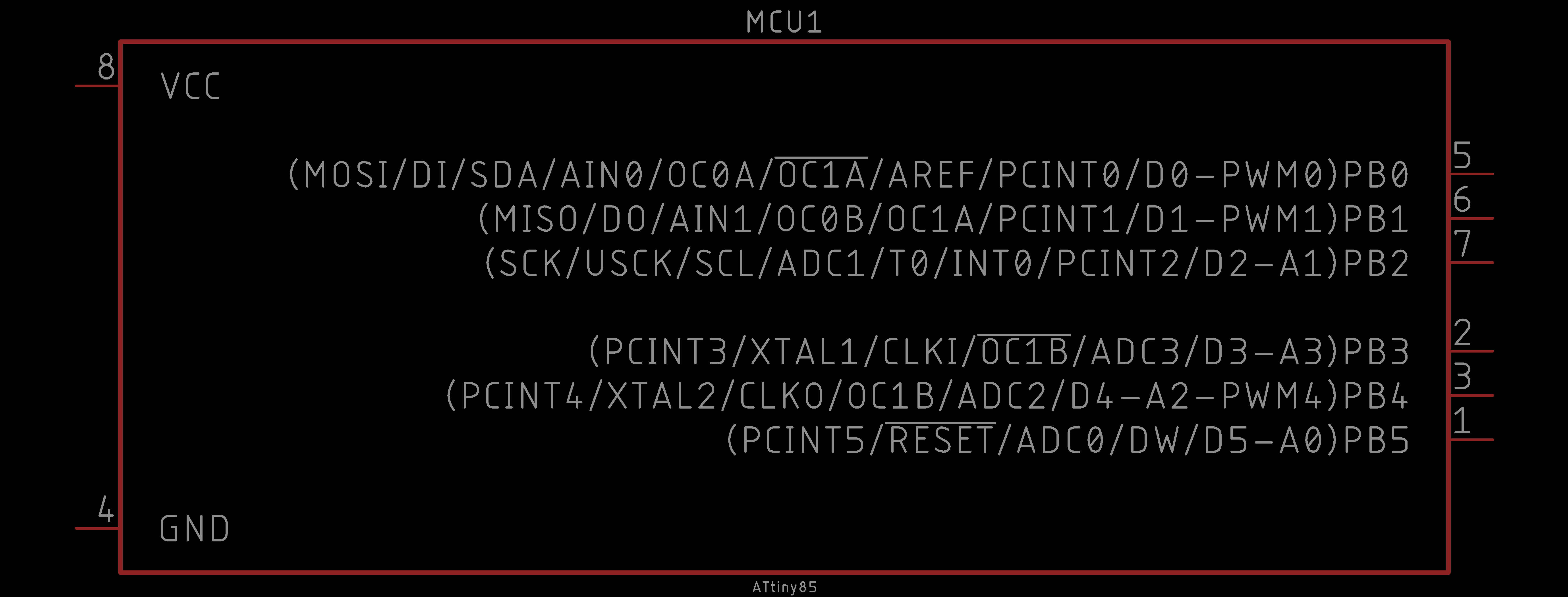
We have the ATtiny85 device in our EAGLE libraries and it is represented as follows:
Observe the similarities and differences. The numbers represent the physical layout of the ATtiny85. However, the order of these numbers do not match the physical layout of the ATtiny85. The reason is because they are organized logically. On the left, the power connections are shown (i.e. VCC and GND). On the right, the GPIO (general purpose input and output) pins are labeled and ordered by port (e.g. PB = port B).
Each of the GPIO pins have one or more functions. The pins that you can program using the ATtinyCore in the Arduino IDE are labeled on the far right inside the parentheses (e.g. D# for a digital input or output pin, A# for an analog input pin, PWM# for a digital PWM or analog output pin). You would use these pins like you would in any typical Arduino sketch.
In this challenge, we will explicitly program the ATtiny85. Follow the ATtinyX5 Microcontroller tutorial closely and program the ATtiny85 to simply blink an LED. We will be using the Arduino UNO as an ISP as our bootloading device, you may skip any mentions of the Sparkfun Pocket AVR Programmer.
Here is the behavior of the challenge simplying blinking an LED:
Note that this solution is NOT the only solution. This is just how we realized it.
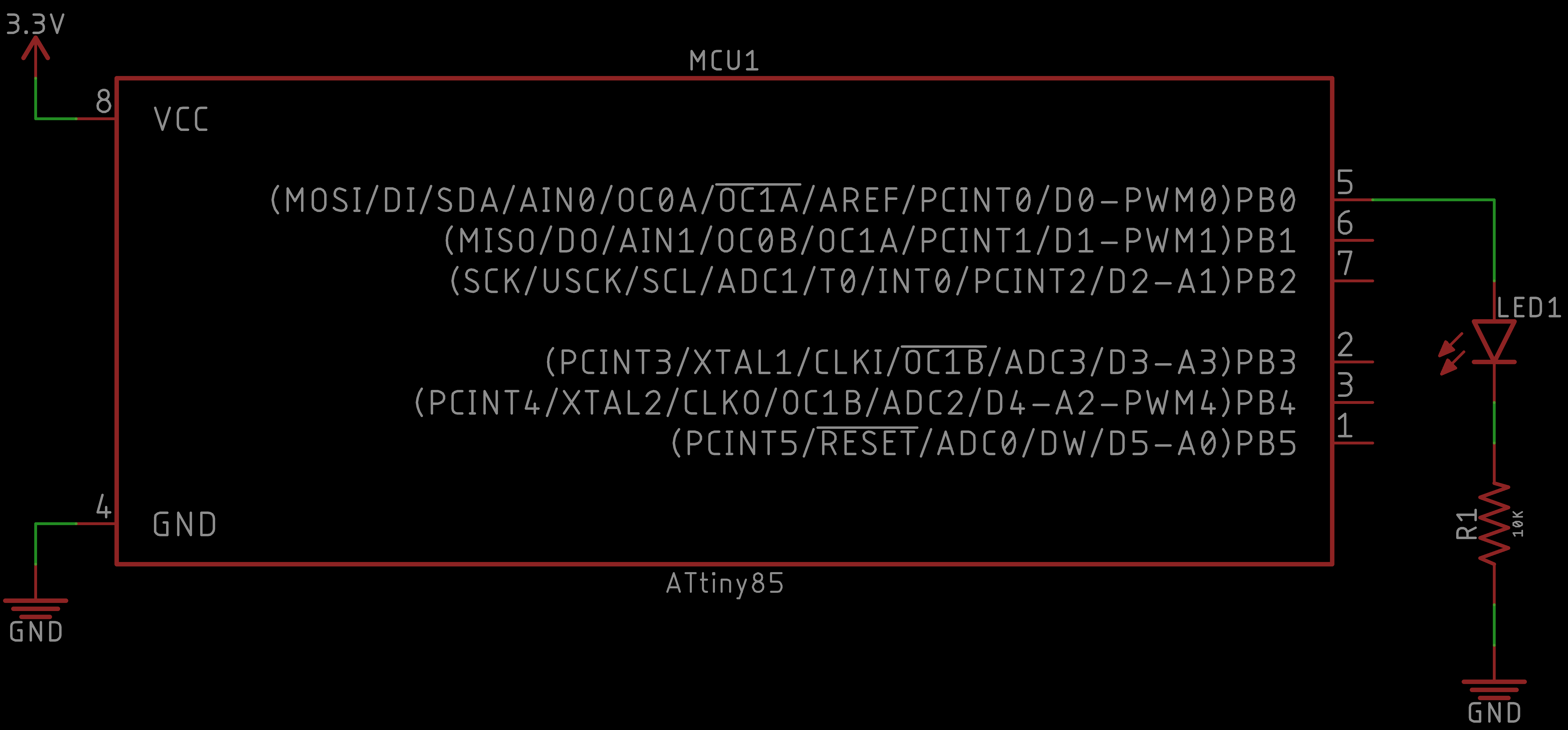
The schematic should be similar to the following:
As for the code, we took the Blink example from the Arduino UNO library of examples and modified the pin number to one appropriate on the Attiny85:
// Trivial program to test the ATtinyX5.
//
// Toggles LED on and off for a fixed period of time.
//  Typical blink sketch.


#define led 0

void setup() {
  // Initialize ATtinyX5 digital physical pin 5
  //	(programming pin 0) as an output.
  pinMode(led, OUTPUT);
}

void loop() {
  // Toggle LED on
  digitalWrite(led, HIGH);
  delay(1000);

  // Toggle LED off
  digitalWrite(led, LOW);
  delay(1000);
}
Again, the results are as follows:
And that is it! Your ATtiny85 should be blinking an LED. This was a trivial example, but it is the first stepping stone to making more interesting functionality.
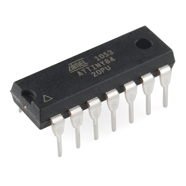
Now we will cover the ATtinyX4 series in general. The ATtiny Programmer's role is only to program the ATtinyX4. To learn about the ATTinyX4, we direct you to our ATtinyX4 Microcontroller tutorial. Since we will be using the Arduino UNO as an In-System Programmer, you need only pay attention to the sections pertaining to the Arduino as an ISP explicitly to bootload and program the ATtiny84.
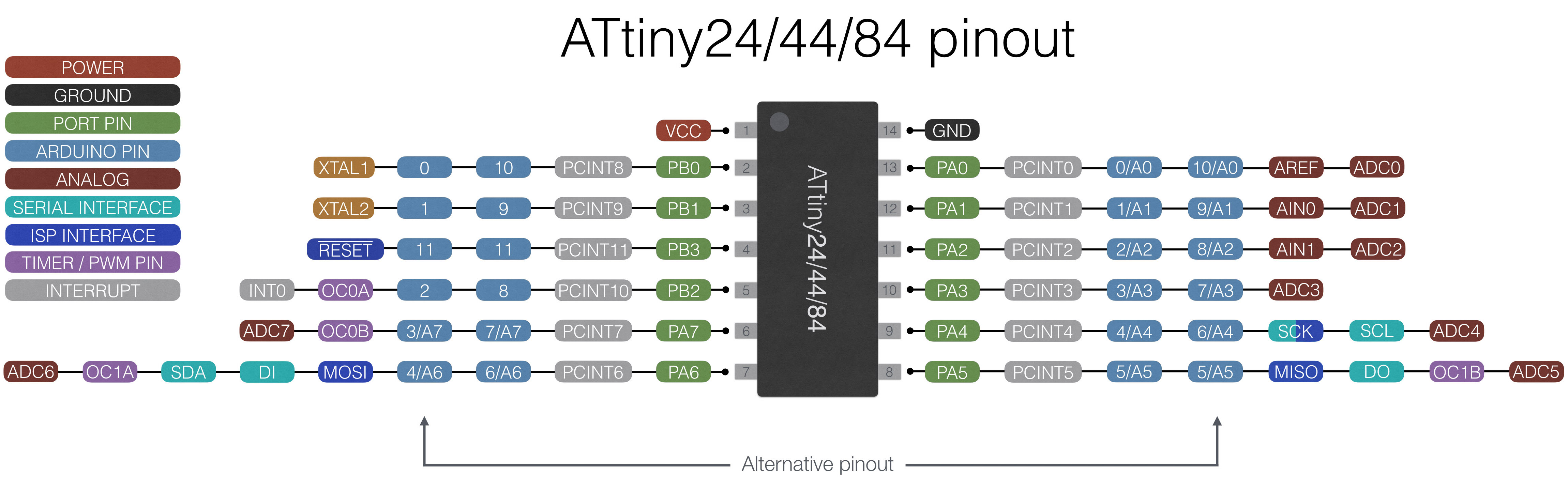
Here we show a reference of the ATtiny84 pinout:
This pinout describes the physical and logical layout of the ATtiny84. The physical layout are the physical pins - pins one through 14 in a counter-clockwise fashion. The logical layout of the ATtiny84 are the numerous labels tied to each physical pin.
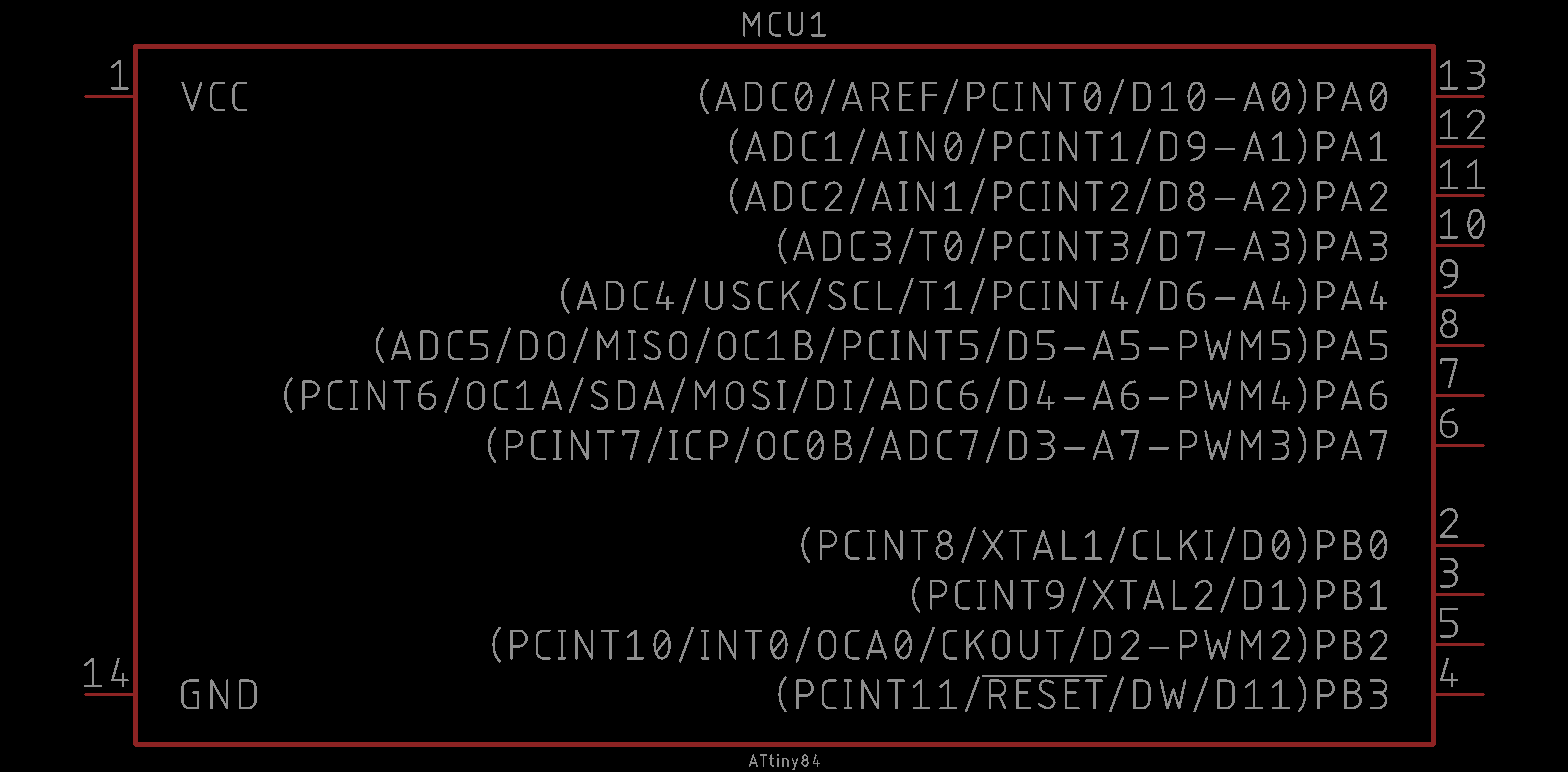
We have the ATtiny84 device in our EAGLE libraries and it is represented as follows:
Observe the similarities and differences. The numbers represent the physical layout of the ATtiny84. However, the order of these numbers do not match the physical layout of the ATtiny84. The reason is because they are organized logically. On the left, the power connections are shown (i.e. VCC and GND). On the right, the GPIO (general purpose input and output) pins are labeled and ordered by port (e.g. PB = port B).
Each of the GPIO pins have one or more functions. The pins that you can program using the ATtinyCore in the Arduino IDE are labeled on the far right inside the parentheses (e.g. D# for a digital input or output pin, A# for an analog input pin, PWM# for a digital PWM or analog output pin). You would use these pins like you would in any typical Arduino sketch.
In this challenge, we will explicitly program the ATtiny84. Follow the ATtinyX4 Microcontroller tutorial closely and program the ATtiny84 to simply blink an LED. We will be using the Arduino UNO as an ISP as our bootloading device, you may skip any mentions of the Sparkfun Pocket AVR Programmer.
Here is the behavior of the challenge simplying blinking an LED:
Note that this solution is NOT the only solution. This is just how we realized it.
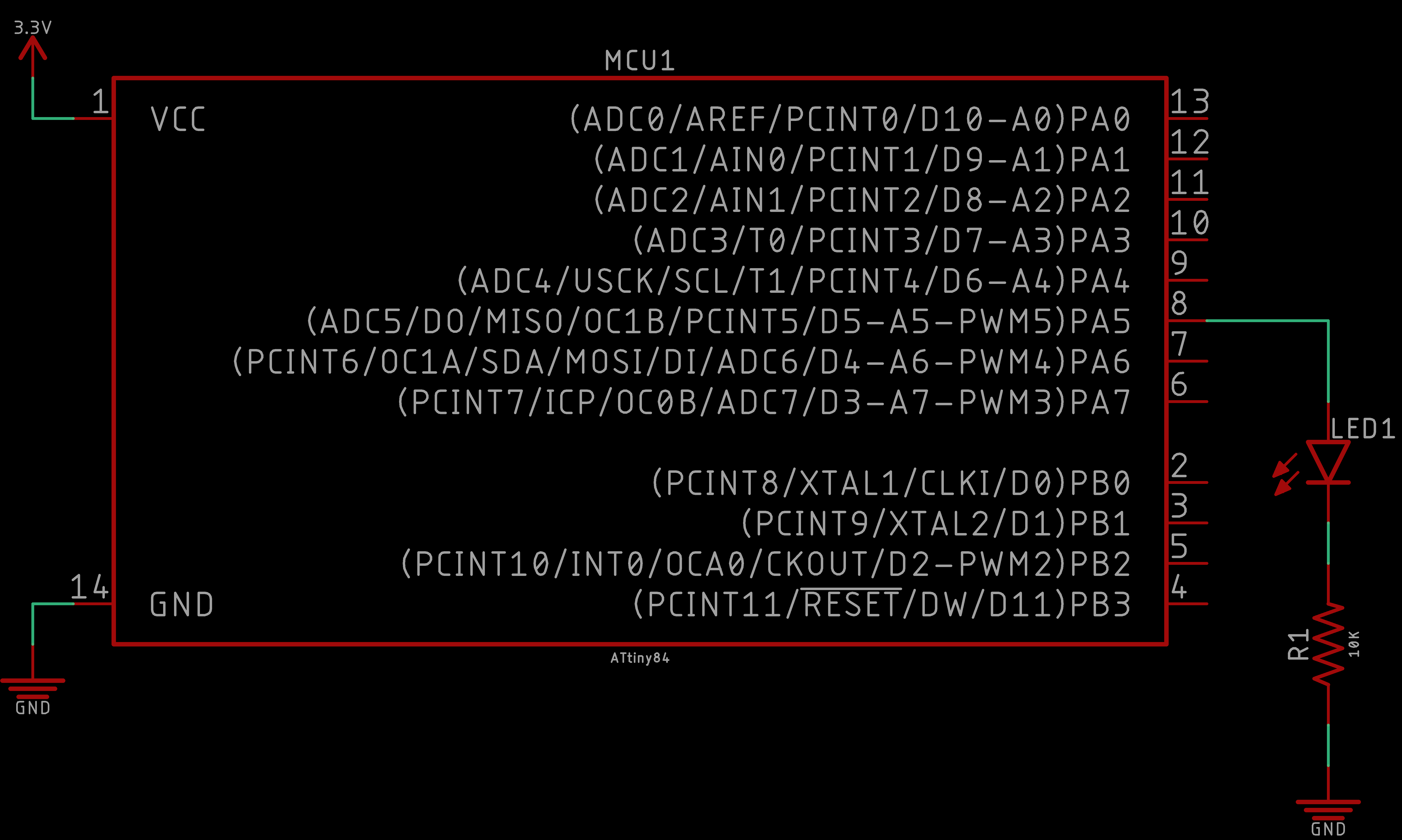
The schematic should be similar to the following:
As for the code, we took the Blink example from the Arduino UNO library of examples and modified the pin number to one appropriate on the Attiny84:
// Trivial program to test the ATtinyX4.
//
// Toggles LED on and off for a fixed period of time.
//  Typical blink sketch.


#define led 5

void setup() {
  // Initialize ATtinyX4 digital physical pin 8
  //	(programming pin 5) as an output.
  pinMode(led, OUTPUT);
}

void loop() {
  // Toggle LED on
  digitalWrite(led, HIGH);
  delay(1000);

  // Toggle LED off
  digitalWrite(led, LOW);
  delay(1000);
}
Again, the results are as follows:
And that is it! Your ATtiny84 should be blinking an LED. This was a trivial example, but it is the first stepping stone to making more interesting functionality.
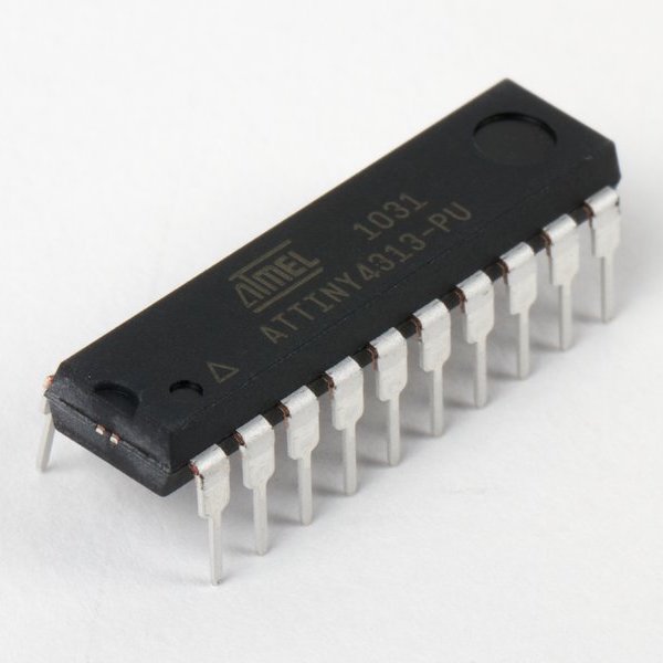
Now we will cover the ATtinyX313 series in general. The ATtiny Programmer's role is only to program the ATtinyX313. To learn about the ATTinyX313, we direct you to our ATtinyX313 Microcontroller tutorial. Since we will be using the Arduino UNO as an In-System Programmer, you need only pay attention to the sections pertaining to the Arduino as an ISP explicitly to bootload and program the ATtiny4313.
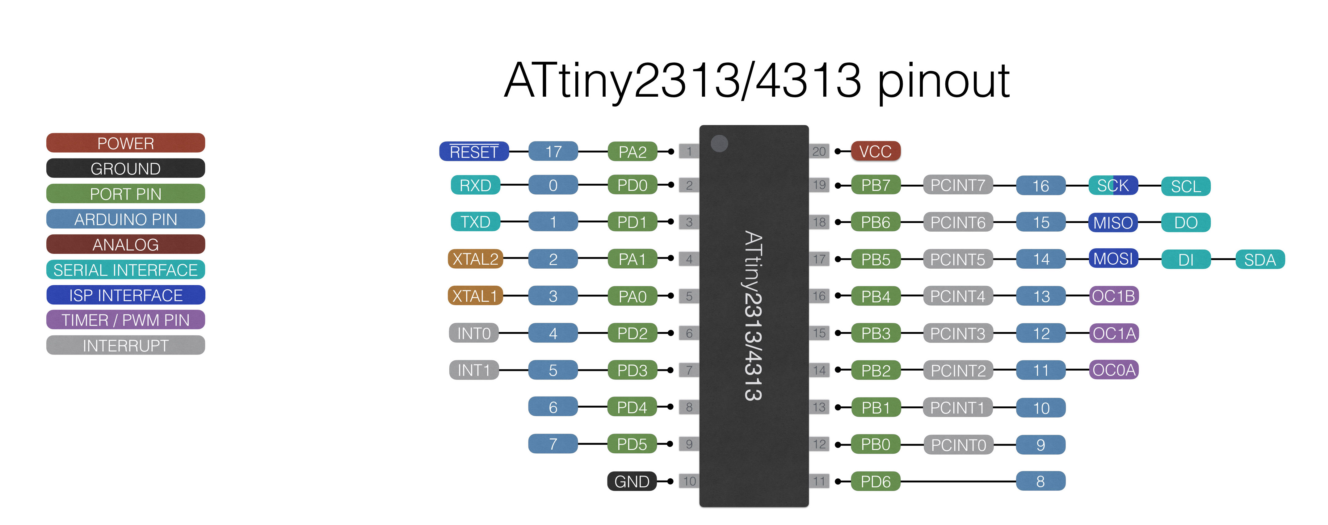
Here we show a reference of the ATtiny4313 pinout:
This pinout describes the physical and logical layout of the ATtiny4313. The physical layout are the physical pins - pins one through 20 in a counter-clockwise fashion. The logical layout of the ATtiny4313 are the numerous labels tied to each physical pin.
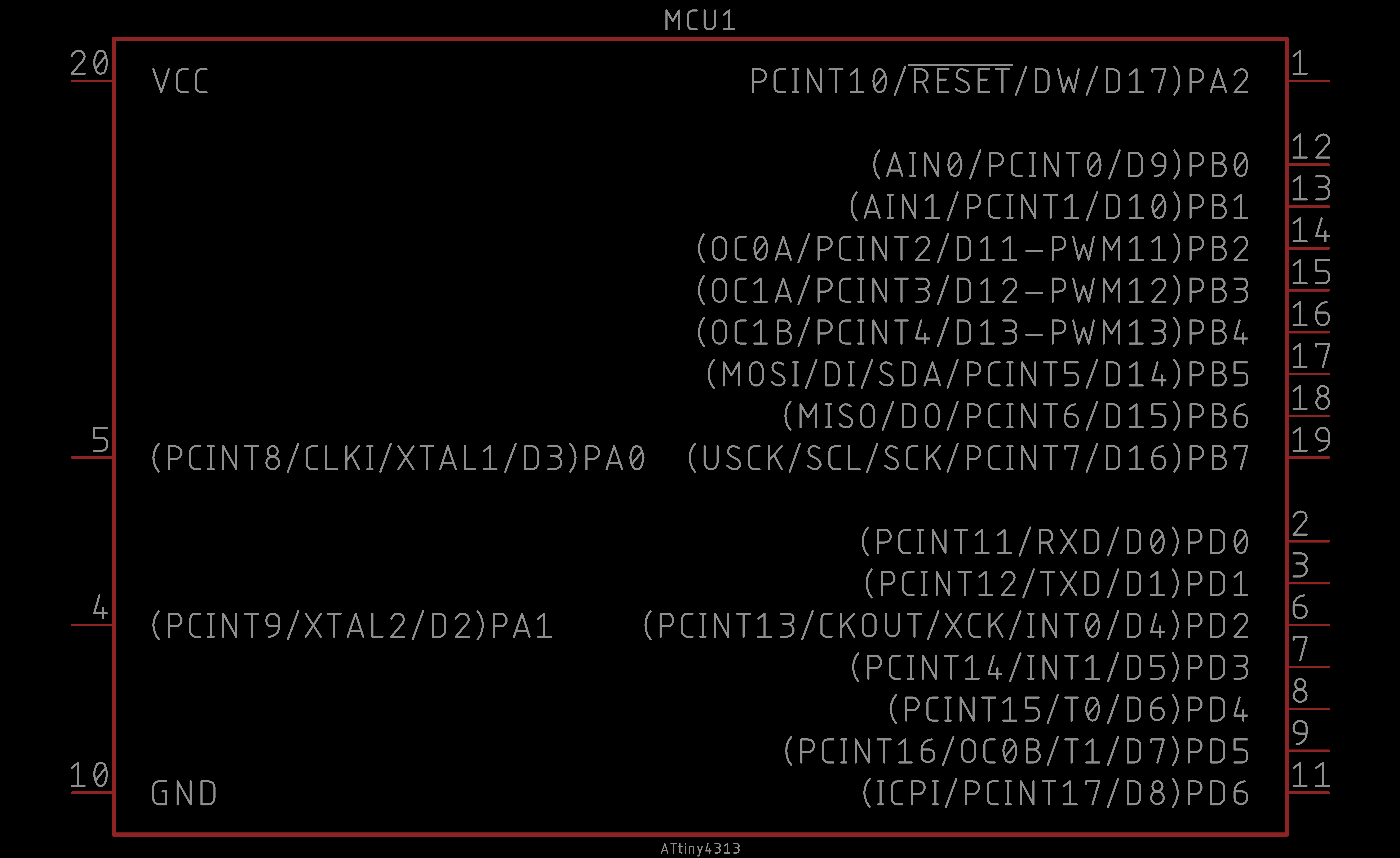
We have the ATtiny4313 device in our EAGLE libraries and it is represented as follows:
Observe the similarities and differences. The numbers represent the physical layout of the ATtiny4313. However, the order of these numbers do not match the physical layout of the ATtiny4313. The reason is because they are organized logically. On the left, the power connections are shown (i.e. VCC and GND). On the right, the GPIO (general purpose input and output) pins are labeled and ordered by port (e.g. PB = port B).
Each of the GPIO pins have one or more functions. The pins that you can program using the ATtinyCore in the Arduino IDE are labeled on the far right inside the parentheses (e.g. D# for a digital input or output pin, A# for an analog input pin, PWM# for a digital PWM or analog output pin). You would use these pins like you would in any typical Arduino sketch.
In this challenge, we will explicitly program the ATtiny4313. Follow the ATtinyX313 Microcontroller tutorial closely and program the ATtiny4313 to simply blink an LED. We will be using the Arduino UNO as an ISP as our bootloading device, you may skip any mentions of the Sparkfun Pocket AVR Programmer.
Here is the behavior of the challenge simplying blinking an LED:
Note that this solution is NOT the only solution. This is just how we realized it.
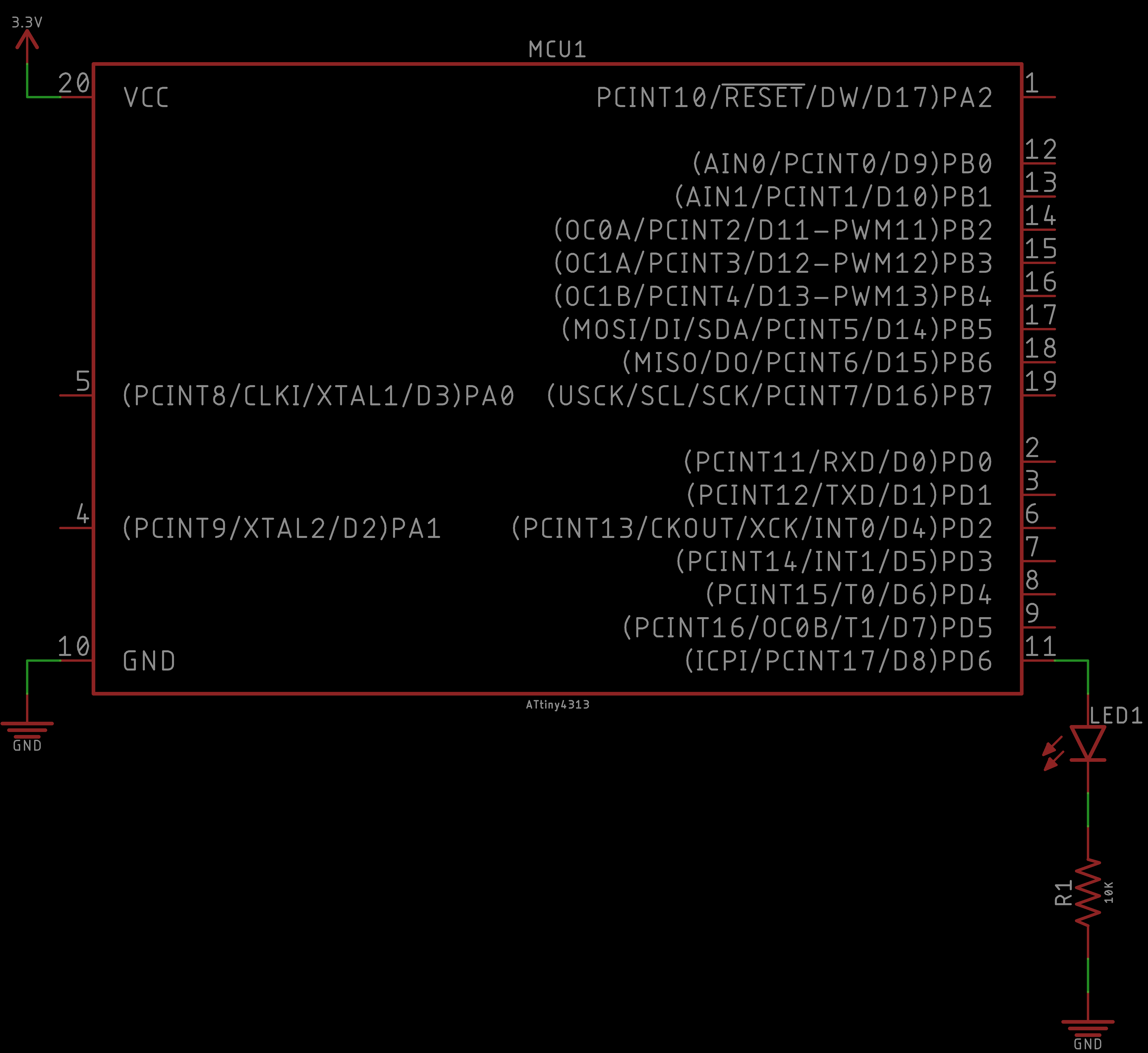
The schematic should be similar to the following:
As for the code, we took the Blink example from the Arduino UNO library of examples and modified the pin number to one appropriate on the ATtiny4313:
// Trivial program to test the ATtinyX313.
//
// Toggles LED on and off for a fixed period of time.
//  Typical blink sketch.


#define led 8

void setup() {
  // Initialize ATtinyX313 digital physical pin 11
  //	(programming pin 8) as an output.
  pinMode(led, OUTPUT);
}

void loop() {
  // Toggle LED on
  digitalWrite(led, HIGH);
  delay(1000);

  // Toggle LED off
  digitalWrite(led, LOW);
  delay(1000);
}
Again, the results are as follows:
And that is it! Your ATtiny4313 should be blinking an LED. This was a trivial example, but it is the first stepping stone to making more interesting functionality.
Hopefully at this point you are feeling two things:
Enter the ATtiny Programmer. An opportunity to create an Arduino UNO shield that programs 3 of the most popular ATtiny variants: ATtinyX5, ATtinyX4, and ATtinyX313. Also a device that is extremely convenient as you will never have to think about the circuits to bootload and program our ATtiny variants ever again!
So if we take what we learned earlier and combine the circuits to program each ATtiny variants individually into one combined circuit we obtain the following:
This is the ATtiny Programmer circuit that we will design and solder! Everything here should look familiar with exception that we removed the Arduino UNO schematic symbol and replaced it with four header pins. However, these header pins should resemble the layout of the Arduino UNO to some degree (it is a little smaller to be efficient on space).
Now that we are familiar with the circuit we need to build, lets design it in EAGLE!
In this module, we will design the ATtiny Programmer PCB. Again, the ATtiny Programmer is an Arduino UNO shield. That is, it will fit snugly onto an Arduino UNO for convenience. Why? Because building the circuit to bootload and program ATtinys is too burdensome to remember the pinout of the SPI pins and it is not worth memorizing such mundane information. As makers, we can make a tool - the ATtiny Programmer Arduino UNO shield to engineer the complexity away!
If you have never used EAGLE or need a refresher, we have an Introduction to EAGLE PCB Design tutorial that we encourage you to follow. This tutorial will also get you started downloading and installing EAGLE. Furthermore, this will get you equipped with the basics so that you can keep up with the pace of the EAGLE content in this project. In these modules, we proceed slowly, however we are not going to go over the basic tools of EAGLE and assume you have the EAGLE Libraries integrated into the EAGLE environment.
First, we will design the ATtiny Programmer schematic.
Then, we shape our board and carefully place our Arduino UNO shield header pins so that it can perfectly fit into an Arduino UNO. This is crucial or else our efforts will be for naught. We layout the rest of the board and place labels along our device for a potential future user and for ourselves.
Finally, we route our PCB and then place some miscellaneous labels to complete the ATtiny Programmer PCB.
This video is optional, but recommended. Here we show you what the ATtiny Programmer looks like in Fusion360 and realize a 3D render of our PCB designed in EAGLE. Then we import our design into OSH Park to get another perspective on our completed board and order our board, if desired.
This completes the ATtiny Programmer PCB design. Next up, we will solder the ATtiny Programmer.
In this module, we will solder our ATtiny Programmer PCB. We have two surface mount (SMD) components and several through-hole components. Although we demonstrate soldering the SMD components with a standard soldering-iron method, you are more than welcome to reflow these components. As for soldering the through-hole components, it is pretty straight-forward except when it comes to the header pins. Take extra caution to make sure that these header pins are soldered on flush and straight so that we can guarantee that the ATtiny Programmer PCB will fit snugly into the Arduino UNO as a shield.
First, we start by filing down the artifacts may contain from panelization in the manufacturing process. Then we solder the SMD components, followed by the header pins. We take advantage of using the Arduino UNO to make sure our header pins are perfectly aligned.
We wrap up the soldering portion by soldering the dual-inline package (DIP) connectors for the ATtinys and then the 10uF capacitor.
This completes the ATtiny Programmer PCB design. Now, let us test our ATtiny Programmer PCB!
Remember, the ATtiny Programmer is not the flashiest of projects. It is a tool made by makers for makers. So in this module, we will be testing our ATtiny Programmer by revisiting the ATtiny tutorials and programming the ATtinys using the ATtiny Programmer instead of constructing the circuit to program the ATtiny using a breadboard. I hope you find this process much faster using the ATtiny Programmer this time around.
Our ATtiny Programmer has slots for all three ATtiny variants; however, you can only program one ATtiny at a time. When you are programming the ATtiny, it communicates with the Arduino UNO and returns the device signature. If you have more than one ATtiny variant in the ATtiny Programmer and you try to bootload or program either one of them, you will get an error that the Arduino is confused because it is receiving an unexpected device signature (even if one of them is the correct device).
From the AVR Microcontrollers tutorial make sure you have your Arduino UNO configured as an In-System Programmer. The process is exactly the same for each ATtiny, except now we no longer need to construct the circuit to bootload and program the ATtinys on a breadboard anymore. Our ATtiny Programmer PCB takes care of this!
Next, we will review each of the ATtiny variants, but now we will program them using the ATtiny Programmer!
Follow the ATtinyX5 Microcontroller tutorial. Except now we will be using the ATtiny Programmer to program the ATtinyX5. Remember, we still need the Arduino UNO configured as an In-System Programmer, but the work of the circuit is now abstracted away into our ATtiny Programmer PCB.
Follow the ATtinyX4 Microcontroller tutorial. Except now we will be using the ATtiny Programmer to program the ATtinyX4. Remember, we still need the Arduino UNO configured as an In-System Programmer, but the work of the circuit is now abstracted away into our ATtiny Programmer PCB.
Follow the ATtinyX313 Microcontroller tutorial. Except now we will be using the ATtiny Programmer to program the ATtinyX313. Remember, we still need the Arduino UNO configured as an In-System Programmer, but the work of the circuit is now abstracted away into our ATtiny Programmer PCB.
The ATtiny Programmer is a great project that introduces several concepts that are widespread in practice. We introduced PCB design and how to create a custom Arduino UNO shield. We created a tool to help us, as a maker, to make faster and to make our lives easier. We were introduced to ATtinys a microcontroller of the same family as the Arduino UNO's ATMEGA328p, just smaller and limited in some cases. However, with this new perspective on ATtinys as an option, you can make real products that are more efficient and abstract away the Arduino UNO board.
You are equipped to use the Arduino UNO as it was truly intended - for development purposes. And now you have knowledge to explore opportunities to reduce cost, reduce area, and increase efficiency with ATtinys (or even the ATMEGA328p). Even though the ATtiny Programmer only programs ATtinys. The same SPI pins and concept are used to program the ATMEGA328p and several other ATtinys and ATMEGA microcontrollers.